


7-2
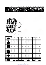
3. Checking S Video Output S-Y
<Purpose>
Check S-terminal video output. If it is incorrect, pictures will not
be displayed correctly in spite of connection to the TV with a S-
terminal cable.
Mode
Video level adjustment in test mode
Signal
Color bars
Test point
S VIDEO OUT (S-Y) connector
(75
Ω
terminated)
Instrument
Oscilloscope
Specification
1.0 ± 0.05 Vp-p
Checking method:
1) In the test mode initial menu “6” Video Level Adjustment, set
so that color bars are generated.
2) Confirm that the S-Y level is 1.0 ± 0.05 Vp-p.
Figure 7-3
4. Checking S Video Output S-C
<Purpose>
This checks whether the S-C satisfies the NTSC/PAL Standard. If
it is not correct, the colors will be too dark or light.
Mode
Video level adjustment in test mode
Signal
Color bars
Test point
S VIDEO OUT (S-C) connector
(75
Ω
terminated)
Instrument
Oscilloscope
Specification
A = 286 ± 30 mVp-p (NTSC)
A = 300 ± 100 mVp-p (PAL)
Checking method:
1) In the test mode initial menu “6” Video Level Adjustment, set
so that color bars are generated.
2) Confirm that the S-C burst is “A”.
Figure 7-4
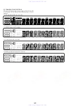
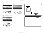
7-2. ADJUSTMENT OF VIDEO SYSTEM
1. Video Level Adjustment (MB-100 BOARD)
<Purpose>
This adjustment is made to satisfy the NTSC/PAL standard, and if
not adjusted correctly, the brightness will be too large or small.
Mode
Video level adjustment in test mode
Signal
Color bars
Test point
LINE OUT (VIDEO) connector
(75
Ω
terminated)
Instrument
Oscilloscope
Adjusting element
RV501
Specification
1.0 Vp-p
Adjusting method:
1) In the test mode initial menu “6” Video Level Adjustment, set
so that color bars are generated.
2) Adjust the RV501 to attain 1.0 Vp-p.
Figure 7-1
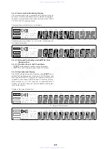
2. Progressive Video Level Adjustment
(MB-100 BOARD)
<Purpose>
This adjustments progressive video output. If it is incorrect, cor-
rect brightness will not be attained when connected to, for instance,
projector.
Mode
Video level adjustment in test mode
Signal
Color bars
Test point
COMPONENT VIDEO OUT (Y)
connector (75
Ω
terminated)
Instrument
Oscilloscope
Adjusting method:
1) In the test mode initial menu “7” Prog Video Level Adjust-
ment, set so that color bars are generated.
2) Adjust the RV901 to attain 1.00
Figure 7-2
+0.04
–0.02
+0.04
–0.02
1.0 Vp-p
+0.04
–0.02
A
1.00
Vp-p
+ 0.04
– 0.02
1.0 ± 0.05 Vp-p
www. xiaoyu163. com
QQ 376315150
9
9
2
8
9
4
2
9
8
TEL 13942296513
9
9
2
8
9
4
2
9
8
0
5
1
5
1
3
6
7
3
Q
Q
TEL 13942296513 QQ 376315150 892498299
TEL 13942296513 QQ 376315150 892498299