background image

Preparing to use the unit

23

DTP-T2000A                          4-121-350-

11(1)

Setting up

Setting up

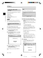
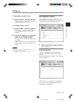
To deactivate access control:

1

Select “Disable”, and click “Setting”.

This allows access from a PC that has been
configured with any IP address.

To activate access control:

1

Select “Enable”, and click “Setting”.

This allows access only from a PC that has
been configured with one of the set IP
addresses.

2

Enter the IP address to be registered,
and then click “Add IP address”.

This registers the IP address to which access
is permitted.
Click on “Delete” next to an IP address that
has already been registered to delete that
address.

Caution

Enter an IP address using one of the following formats:
• xxx.xxx.xxx.xxx (xxx = 0-255)
• xxx.xxx.xxx.xxx/yy (xxx = 0-255, yy = 0-32)

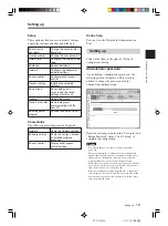
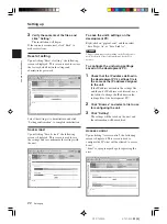
Self-diagnostic program

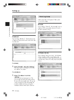
Upon clicking “Self-diagnostic program”, the
following screen is displayed. This screen is used
to perform a variety of self-diagnostic tests.

1

Click on the process to be performed.

The test will begin.

Restart of dsnetm

“dsnetm” is a program used to communicate
between the TCP/IP sockets on the unit and a
host PC.
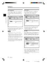
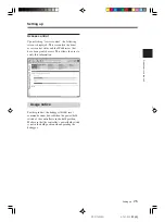
Upon clicking “Restart of dsnetm”, the following
screen is displayed.

Click “Restart” to restart dsnetm and display the
restart status. After completing the restart, the
following screen is displayed.

Содержание DTP-T2000A

Страница 1: ... This manual contains safety precautions for the prevention of accidents and instructions for the use and handling of this product Read this manual carefully and use the product in a safe manner After reading the manual store it in an accessible location for future reference 4 121 350 11 1 ...

Страница 2: ...battery The lithium coin memory back up battery inside this product contains Perchlorate The following statement is required by the State of California USA Perchlorate Material special handling may apply See http www dtsc ca gov hazardouswaste perchlorate For customers in the U S A and Canada This Class A digital apparatus complies with Canadian ICES 003 This device complies with Part 15 of the FC...

Страница 3: ...eaning the unit exterior INSTALLATION Water and moisture Do not use the powerline operated unit near water for example near a bathtub washbowl kitchen sink or laundry tub in a wet basement or near a swimming pool etc Power cord protection Route the power cord so that it is not likely to be walked on or pinched by items placed upon or against it paying particular attention to the plugs receptacles ...

Страница 4: ...ation When the unit exhibits a distinct change in performance this indicates a need for service Servicing Do not attempt to service the unit yourself as opening or removing the exterior casing may expose you to dangerous voltage or other hazards Refer all servicing to an authorized service center Refer to the contact information on the back cover to receive instructions on obtaining repair replace...

Страница 5: ... the unit Connecting to a network 15 Unit or accessories necessary for connecting 15 Connection diagrams 15 Connecting peripherals 16 Setting up 17 Information necessary for setup 17 Preparing for setup 17 Turning on the unit 17 Confirming information settings 18 Starting the Administration Tool 18 Setting up 19 Showing status 24 Usage notice 25 Chapter3 Appendices Troubleshooting 26 Specification...

Страница 6: ...mage to the unit could result The socket outlet shall be installed near the equipment and shall be easily accessible Only trained professionals should attempt electrical socket outlet installation Use and handling Do not use the unit or accessories outdoors Do not throw or drop the unit or accessories or expose the devices to strong physical shock Handle the analog stick with care Do not forcibly ...

Страница 7: ...t the power plug for the unit from the electrical outlet Moisture condensation If the unit or disc is brought directly from a cold location to a warm one moisture may condense on the lens inside the unit or on the disc Should this occur the unit may not operate properly In this case remove the disc and then turn off and unplug the unit Do not put the disc back in until the moisture evaporates this...

Страница 8: ... DTP H120 sold separately If the unit is used with the controller and aerial in close proximity to each other radio frequency interference from the controller will interfere with the wireless LAN signal and can cause an increase in loss of data packets DRIVE SELECT POWER SYSTEM INIT NETWORK INIT UMD CONTROLLER GPO GPI ON OFF DVD 0 7 6 5 4 3 2 1 0 1 2 3 4 5 6 7 1 Z Z SELECT START VOL Aerial Separat...

Страница 9: ...processor allows software data etc to be easily sent and received through the development PCs and networks A direct network connection can be established for easy installation and additions Also the load on development PCs can be reduced Two types of drives are built in a UMDTM drive and a DVD ROM drive which is used during development A switch is used to select the desired drive For proper operat...

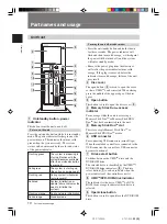
Страница 10: ... disc cover 2 4 Memory Stick DuoTM access indicator Turns orange while the unit is accessing a Memory Stick DuoTM or Memory Stick PRO DuoTM that has been inserted into the unit 5 Memory Stick DuoTM slot This slot accepts Memory Stick DuoTM or Memory Stick PRO DuoTM media 6 USB connector For connecting USB connectors mini B type When the included controller is connected to the USB connector the con...

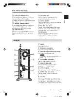
Страница 11: ... a stereo mini plug can be connected here qh GPI switch These are eight dip switches that are user definable by PSPTM software developers Unit rear EXT RF EXT FOOT SW DC IN 19 5V L AUDIO OUT R 1 Aerial For wireless LAN use 2 Extension connector For use by service personnel only 3 Dedicated connector for servicing For use by service personnel only Caution Usage of this port may cause irreparable da...

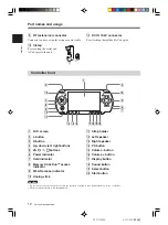
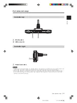
Страница 12: ...button qh Volume button qj Display button qk Sound button ql Select button w Start button 2 4 8 9 q qa qs 1 qf qg qh qjqkqlw 3 5 6 7 qd Part names and usage 9 RF extension connector Connects to an access point using a coaxial cable q Clamp For securing the aerial and AC adaptor to the unit qa DC IN 19 5V connector For attaching the included AC adaptor Part names and usage Caution Do not cover or i...

Страница 13: ... power hold switch of the controller is in the hold position Make sure that the controller s power hold switch is not in the hold position when operating the debugger Before turning off the unit check that the controller is not in hold mode If the unit is turned off with the power hold switch of the controller in the hold position the unit will not turn off properly If this happens disconnect the ...

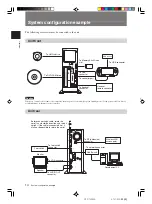
Страница 14: ...or Foot switch Monitor Speaker To network connector Wireless LAN access point To RF extension connector To USB connector Development PC Hub Switch System configuration example System configuration example To AUDIO OUT connector Caution When you connect or disconnect the controller turn off power to the unit keep it in standby mode If the power is left on it may result in damage to the unit or the ...

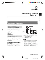
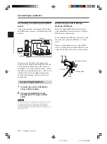
Страница 15: ... unit and a development PC in the following manner At this time the following static IP addresses are automatically set for the unit IP address 192 168 0 10 Subnet mask 255 255 255 0 Caution The IP address and subnet mask settings are default factory settings When the network settings for the unit are modified these settings are also modified accordingly To modify the IP address start up both the ...

Страница 16: ...ng a network cable Caution When using the wireless LAN function keep the controller away from the unit s aerial If the unit is used with the controller and aerial in close proximity radio frequency interference from the controller can affect the radio waves of the wireless LAN Hub Switch Controller The unit Development PCs Monitor Network Connecting to a network Connecting to a network When using ...

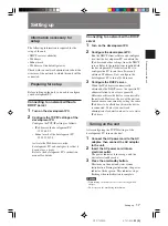
Страница 17: ... AC adaptor to the unit 2 Insert the AC power cord into an electrical outlet The power indicator turns orange and the unit enters standby mode 3 Press the on standby button This turns on the unit and starts system initialization During initialization the power indicator flashes green This indicator stops flashing when initialization is complete Caution When turning on the unit be sure to use the s...

Страница 18: ...ayed 3 Select the display language for the administration tool The login screen is displayed Select the language for example English here Login Log in with a user name and password Enter the user name and password 1 Enter the user name and password as follows To log in as the administrator enter the Administrator user name and password as follows user name Administrator password Administrator Thes...

Страница 19: ...word may be seven or eight characters long Passwords fewer than seven characters long are not allowed Also if nine or more characters are entered only the first eight characters are set as the password If an error is made in entering the password or the values entered into the Password and Retype password fields do not match an error message is displayed If this occurs enter the password again Set...

Страница 20: ...ed only the first eight characters are set as the password If an error is made in entering the password or the values entered into the Password and Retype password fields do not match an error message is displayed If this occurs enter the password again Date time Upon clicking Date time the following screen is displayed This screen is used to configure the date time and time zone Enter values for ...

Страница 21: ...propriate directories on the development PC and click Update The following screen appears Caution Upon clicking Setting confirmation see the step below the versions of files that are already installed and the versions of the update files are checked to confirm whether the update files are more recent and to confirm the dependency relationships between files This check is not performed if No versio...

Страница 22: ...on psptool conf and then select Save Target As or Save Link As Caution This procedure may vary depending on the Web browser used For details refer to the instructions for the Web browser To configure the unit using settings saved on the development PC 1 Check that the IP address defined in the development PC s settings file is the same as the IP address assigned to the unit If the IP address defin...

Страница 23: ...o an IP address that has already been registered to delete that address Caution Enter an IP address using one of the following formats xxx xxx xxx xxx xxx 0 255 xxx xxx xxx xxx yy xxx 0 255 yy 0 32 Self diagnostic program Upon clicking Self diagnostic program the following screen is displayed This screen is used to perform a variety of self diagnostic tests 1 Click on the process to be performed T...

Страница 24: ...e unit will enter standby mode The power can also be turned off thereby putting the unit into standby mode by pressing the on standby button on the front of the unit Setting up Showing status Click on the items to the right of Show status to verify the settings Network Upon clicking Network the following screen is displayed This screen allows the user to verify the unit s network settings Software...

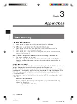
Страница 25: ...tatus and the IP addresses that have been granted access This allows the user to verify this information Usage notice For this product the debugger dstdb reset command cannot be used when the power hold switch of the controller is in the hold position Make sure that the controller s power hold switch is not in the hold position when operating the debugger Setting up Setting up ...

Страница 26: ... disconnect and reconnect the power The settings will then be displayed on the controller About checking settings Check that you can access the currently connected network using the values for IP address subnet mask that have been configured For details please consult your network administrator To check whether the development computer and the unit are correctly communicating start the ping comman...

Страница 27: ...the unit After checking the above items start the ping command from the development PC Then check the indicator next to the network connector on the rear of the unit When the indicator flashes orange The communications are functioning properly When the indicator is not turned on The communications are not functioning properly This may be due to disconnected cables damaged connections or a unit mal...

Страница 28: ... d Weight including the cable Approx 370 g AC adaptor DTP H100 Power Input voltage AC 100 240V 10 Output voltage DC 19 5 V Rated frequency 50 60Hz 2 Power consumption 1 6A 100V 0 7A 240V External dimensions 160 x 38 x 80 mm w h d Weight Approx 570 g Supplied accessories Instruction manual x 1 AC power cord for use in Oceania x 1 AC power cord for use in Europe x 1 AC power cord for use in Korea x ...

Страница 29: ... 350 11 1 U S and foreign patents licensed from Dolby Laboratories A portion of the PSPTM system software requires the following copyright notice This software is based in part on the work of the Independent JPEG Group Specifications Specifications ...

Страница 30: ...nse agreement and or development agreement with Sony Computer Entertainment Inc or its affiliates Other than as expressly set forth by SCEI and or any of its affiliates except to the extent prohibited by applicable laws SCEI and or any of its affiliates shall not be liable for any damages including special incidental or consequential damages or fees arising out of the use or inability to use this ...

Страница 31: ...Appendices Inst B5 Ver 4 0 31 DTP T2000A 4 121 350 11 1 ...

Страница 32: ...direct FAX 1 650 655 5511 direct Without obtaining the consent of the owner no part of the content of this document may be copied pursuant to the provisions of the Copyright Act is a registered trademark and and UMD are trademarks of Sony Computer Entertainment Inc SONY and are registered trademarks and Memory Stick Duo Memory Stick PRO Duo and are trademarks of Sony Corporation 2008 Sony Computer...

Отзывы: