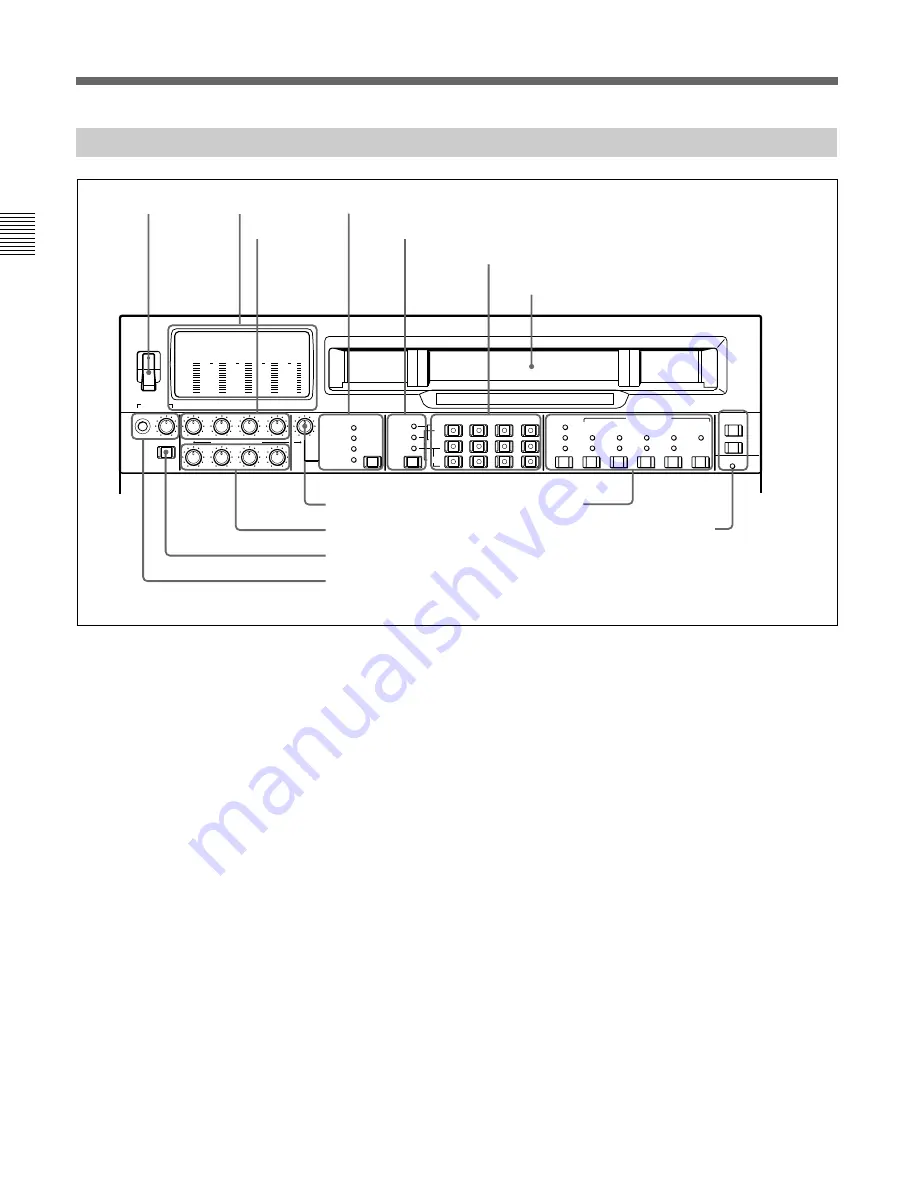
2-1 Control Panels
Chapter 2
Location and Function of Parts
2-2
Chapter 2
Location and Function of Parts
2-1-1 Upper Control Panel
-20
PHONES
DISPLAY
FULL/FINE
CH-1
CH-2
CH-3
CH-4
VIDEO
POWER
REC
PULL FOR VARIABLE
PB
ON
OFF
-80
-20
-30
-40
-10
0
dB
-80
-20
-30
-40
-10
0
dB
-80
-30
-40
-10
0
dB
-80
-20
-30
-40
-10
0
dB
0
-2
2
-4
COMPOSITE
COMPONENT
(Y-R,B)
SDI
VIDEO INPUT SELECT
AUDIO SELECT
INPUT
EXT
MIXING
L
R
CH-1
CH-2
CH-3
CH-4
LTC
TC
AUTO
VITC
INT
EXT
PRESET
REGEN
FREE
RUN
REC
RUN
DF
NDF
ON
1(9P)
TC GENERATOR
VITC
DIGITAL
REMOTE
SDT I
(VIDEO&AUDIO)
MONITOR
SDI
AES/EBU
REC CH
ANALOG
2(50P)
RS232C
1
POWER switch
This powers the unit on and off. When the unit is
powered on, the level meters
2
and the fluorescent
display in the lower control panel light.
To power the unit off, press the side of the POWER
switch marked “OFF”.
2
Level meters
These show the audio levels of channels 1 to 4
(recording levels in recording mode or E-E mode
1)
and
playback level in playback mode) and the video levels
of input composite video signals.
There are two modes for audio level indications:
FULL and FINE, selected by the DISPLAY FULL/
FINE switch
9
.
1) E-E mode: Abbreviation of “Electric-to-Electric mode”.
In this mode, video and audio signals input to the VTR
are output after passing through internal electric circuits,
but not through magnetic conversion circuits such as
heads and tapes. This can be used to check input signals
and for adjusting input signal levels.
..........................................................................................................................................................................................................
3
REC (recording) controls
These individually adjust the recording levels on
channels 1 to 4.
To set the recording level, put the unit in E-E mode,
pull out the control knobs and adjust the level while
watching the level meters
2
.
When the control knobs are pushed in, the recording
levels return to the preset levels (0 dBm reference level
for an input of +4 dBm), and cannot be adjusted.
These controls do not function when SDTI video input
is selected.
For details of selecting the E-E mode, see the description of
the REC button in the tape transport control section (see
page 2-14) and the PB.EE button in the monitor/menu/
display setting section (see page 2-8).
1
POWER
switch
2
Level meters
3
REC controls
4
VIDEO INPUT SELECT switch and indicators
5
Audio selection function selector switch and indicators
7
VIDEO control
8
PB controls
9
DISPLAY FULL/FINE switch
0
PHONES jack and control
!¡
Time code setting
section
!™
REMOTE buttons and RS-232C indicator
6
Audio signal selection buttons
Cassette compartment
Содержание DNW-75
Страница 1: ...DIGITAL VIDEOCASSETTE RECORDER DNW 75 75P OPERATION MANUAL English 1st Edition Revised 4 ...
Страница 8: ......
Страница 32: ......
Страница 44: ......
Страница 106: ......
Страница 116: ......
Страница 120: ...Printed in Japan 2001 07 13 1999 Sony Corporation B P Company DNW 75 75P SYL 3 867 619 05 1 ...


