– 13 –
SECTION 2
TEST PROCEDURES
Testing a SONY CM-Mx300/CM-Bx200 (Analog Only) on a
HP8924C/E
The following pages illustrate how to set up and perform basic
analog and digital cellular tests on a SONY CM-Mx300/CM-
Bx200 Handset. The step-by-step instructions are for those
unfamiliar with the SONY CM-Mx300/CM-Bx200 Handset or
with a HP8924C/E CDMA Radio Test Set. The tests discussed
are general tests that can be used to determine if the Handset is
operating properly. This does not reflect all of the tests needed
to fully test specification compliance.
Performing Analog Measurements
Getting Started
1.
Turn on the Hewlett Packard HP8924C/E CDMA Radio
Test Set and wait for it to go through its initialization
routine.
2.
Since the HP8924C/E powers up into the Digital CDMA
test mode, switch over to the Analog AMPS mode by
pressing the “SHIFT” + “RFANL” keys in the “ANALOG
SCRNS” area of the front panel.
3.
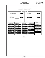
The “CALL CONTROL” screen will appear, letting you
know that you are in the Analog AMPS test mode.
4.
Select the “Cntrl Chan” field. Then change the setting to
the Handset’s active NAM “1
ST
PAGING CHANNEL”
value. See “Service Programming Sony’s CM-Mx300/CM-
Bx200 Handset” for more information.
5.
Press the “Shift” + “TESTS” keys to go to the Config Scrn
screen and set "RF Level Offset" to "ON", select the “RF
In/Out field and enter loss. Make sure that the "RF Input
and Output Ports" settings are set to "RF IN/OUT". Press
the "SHIFT" + "RF ANL" keys to get to the "CALL
CONTROL" screen.
6.
Select the “Amplitude” field and change the setting to
-50dBm or higher to ensure a strong test signal.
7.
Select the “SID” field. Then change the setting to the
Handset's active NAM, “HOME SYSTEM ID” value. See
“Service Programming Sony’s CM-Mx300/CM-Bx200
Handset” for more information.
8.
Select the “MS ID” field and change the setting to match
the Handset's active NAM, “MIN2” and “MIN1” values
(i.e., Telephone Number). See “Service Programming
Sony’s CM-Mx300/CM-Bx200 Handset” for more
information.
9.
Put the “CALL CONTROL” screen in the active mode by
selecting “Active” from the command execution group menu.
10.
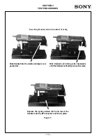
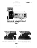
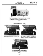
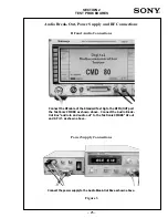
Insert the Standard Test Jig Cable between the Audio
Break-Out Box and the base of the Standard Test Jig as
shown in Figure 1.
11.
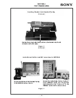
Insert the Handset into the Test Jig as shown in Figure 2.
12.
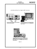
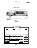
Connect the Audio Break-Out Box and the RF cable of the
Test Jig to the power supply and to the HP8924C/E as
shown in Figure 3. Make sure that the Audio Break-Out
Box "EXT Audio" switch is set to the "OFF" position.
13.
Press the “POWER” key on the Handset and wait for the
Handset to power up. After the Handset has detected the signal
from the HP8924C/E, it will sense that it is in its Home System
and you will see the RSSI indicator display a strong signal. If the
roaming indicator “R” comes on, then the settings in the
HP8924C/E may be wrong. Recheck the settings if necessary.
Power Level Measurements
14.
Select the “Register” command from the command
execution group menu to register the Handset to the
HP8924C/E. If the registration is successful, the Handset’s
ESN and telephone number will be displayed at the top of
the “CALL CONTROL” screen.
15.
Select the “Display” fields and change the setting to
“Meas.” The top of the “CALL CONTROL” screen will
change formats and display Handset transmitter data.
16.
Under the section “Voice Channel Assignment,” edit the
parameters to the voice channel on which you wish to
measure the power level. Enter the initial power level at
which you would like to test. If you want to use a specific
SAT frequency, you can set that in this section as well.
17.
Select the “Page” commands from the command execution
group menu to place a call to the Handset.
18.
Press the “SEND” key on the Handset when it starts ringing.
This will answer the call. The “Connect” indicator at the top
of the “CALL CONTROL” screen will be highlighted once
the call connection has been established.
19.
Change the “TX Power” field’s unit to measure “dBm,”
and note the transmitted power level from the Handset.
Remember to adjust for cable and Test Jig loss between the
Handset and the HP8924C/E. The measured power level
should be within specification limits.
20.
Note the “TX Frequency Error” measurement for the
current power level and voice channel. This measurement
is continuously displayed.
21.
If you want to change the Handset's output power level on
this voice channel, select the “Order” field and enter the
power level that you want to change (0-7).
22.
Repeat step 21 to change to other power level settings on
the current voice channel. The transmitted power from the
Handset, as well as the transmitter frequency error, will be
continuously displayed.
Handoffs
23.
To change voice channels during a call, edit the “Chan:”
setting in the “Voice Channel Assignment” area of the
“CALL CONTROL” screen.
24.
Select the “Handoff” command from the command
execution group menu to change voice channels. The
channel number next to the “Chan:” field in the “Voice
Channel Assignment” area will change, confirming that the
Handset has changed channels.
25.
Repeat steps 23 and 24 to change to other voice channels
during the same call.


