1-5
CDP-D12
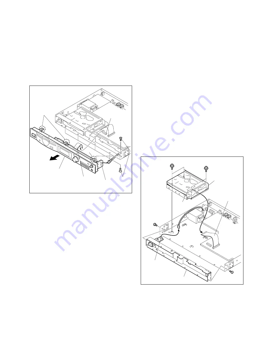
1-3-2. Front Panel
1.
Remove the cover. (Refer to Section 1-3-1.)
2.
Disconnect the flexible card wire from the connector
(CN10) on the MAIN board.
3.
Disconnect the connector (CN571) on the HP board.
4.
Remove the five step tapping screws, disengage the
claws at the three positions, and remove front panel in
the direction of the arrow.
Step
tapping
screws
Front panel
Flexible card wire
Claw
Claws
MAIN board
(CN10)
HP board
(CN571)
1-4. Replacement of Main Parts
n
Before starting the parts replacement, turn off the power
and disconnect the plug from the outlet.
1-4-1. Removing and Installing the CD
Mechanism Deck Assembly
(MG-398SC-121) and Internal Parts
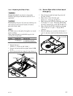
1. CD mechanism deck assembly (MG-398SC-121)
1.
Remove the cover and the front panel.
(Refer to 1-3 “Removing the Cabinet”.)
2.
Disconnect the harness from the connector (CN3) on
the AC/SW board.
3.
Remove the four screws (BVTT3
x
5) and remove the
chassis (SUB).
4.
Remove the four screws (PSW3
x
5) and remove the
CD mechanism deck assembly.
5.
Disconnect the flexible card wire from the connector
(CN1) on the SERVO board.
PSW3
x
5
PSW3
x
5
BVTT3
x
5
BVTT3
x
5
CD mechanism deck
assembly
Flexible card wire
SERVO board
(CN1)
AC/SW board
(CN3)
Chassis (sub)
Содержание CDP-D12
Страница 1: ...COMPACT DISC PLAYER CDP D12 SERVICE MANUAL 1st Edition ...
Страница 4: ......
Страница 34: ......
Страница 42: ......
Страница 48: ......
Страница 54: ...Printed in Japan Sony Corporation 2003 10 16 2003 CDP D12 UC CE CN E 9 976 920 01 ...


