5-23
BVW-55 P2
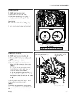
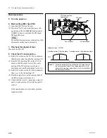
(4) Turn the tracking VR (RV100) so that the
output level of the center portion of RF
envelope waveform is maximized.
(5) Turn the tracking VR (RV100) clockwise so
that the center portion of the RF envelope
waveform makes 80% of its maximum output
level.
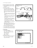
(6) At the state of (5), check that the RF enve-
lope waveform satisfies specification 1.
n
If the level fluctuates, read the average level.
(7) If the level fluctuates, turn the tracking VR
(RV100) on the SV-206 board so that the
output level in the center portion of the RF
envelope waveform is maximized, and check
that the fluctuation amounts satisfy the
specification 2.
If specifications 1 and 2 are not satisfied, perform
the adjustment (at the Drum Entrance Side or the
Drum Exit Side) in steps 19 and later.
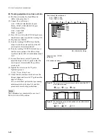
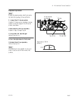
12. F. FWD and REV modes
(1) Press the PLAY button to play back the
CR2-1B.
(2) Put the unit into the F. FWD
x
5 mode and
check that the RF waveform satisfies the
specification 3.
(3) Put the unit into the REV
x
5 mode and check
that the RF waveform satisfies the specifica-
tion 3.
If specification 3 is not satisfied in each mode,
perform the adjustment (at the Drum Entrance
Side or the Drum Exit Side) in steps 19 and later.
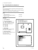
13. REV
x
x
x
x
x
10 mode to PLAY mode
(1) Press the PLAY button to play back the
CR2-1B.
(2) Put the unit into the REV
x
10 mode once.
Three seconds later, put the unit into the
PLAY mode again.
Check that the RF envelope waveform
returns to the maximum level with the even
level. (Specification 4)
(3) Repeat changing the mode REV
x
10 to
PLAY three times, check that the waveform
satisfies the specification 4 on every time.
14. Adjust the drum PG phase
(Refer to Section 6-2-1.)
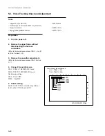
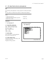
5-5. Video Tracking Check and Adjustment
.
Alignment tape : CR2-1B
(D109 Lit)
.
Alignment tape : CR2-1B
(D109 Dark)
.
Alignment tape : CR2-1B
(D109 Dark)
G
H
J
E
F
I
F
E
>
0.9
The fluctuation value in each portion of a waveform should be
less than 10 %.
Spec.2:
,
G
H
>
0.9
,
I
J
>
0.9
C
D
A
B
B
A
>
0.8
The output level of the waveform should be more than 80 %
of the maximum value.
Spec.1:
,
C
A
>
0.8
,
D
A
>
0.8
B
A
x
100
>
80 %
Spec. 3:
A
B
A
B
Spec.4
(OK)
(NG)
(NG)
[Drum entrace side]
[Drum exit side]
Returning with even level.
Содержание BVW-55
Страница 1: ...VIDEOCASSETTE RECORDER BVW 55 MAINTENANCE MANUAL Part 1 1st Edition Serial No 10001 and Higher ...
Страница 4: ......
Страница 8: ......
Страница 50: ...1 40 BVW 55 1 2 3 4 5 6 7 8 9 d l s d l 1 15 Fixtures and Adjustment Equipment List ...
Страница 58: ......
Страница 106: ......
Страница 116: ......
Страница 130: ......
Страница 148: ......
Страница 150: ...Printed in Japan Sony Corporation 1999 3 08 Broadcasting Professional Systems Company 1999 BVW 55 UC E 3 202 213 01 1 ...
Страница 151: ...VIDEOCASSETTE RECORDER BVW 55 MAINTENANCE MANUAL Part 2 Volume 1 1st Edition Serial No 10001 and Higher ...
Страница 154: ......
Страница 158: ......
Страница 169: ...1 9 BVW 55 P2 1 2 Fixtures and Adjustment Equipment List 1 2 3 4 5 6 7 8 9 d l s d l ...
Страница 176: ......
Страница 272: ......
Страница 384: ......
Страница 386: ...Printed in Japan Sony Corporation 1999 7 08 Broadcasting Professional Systems Company 1999 BVW 55 UC E 9 967 828 01 ...
Страница 392: ......
Страница 396: ...1 2 BVW 55 ...
Страница 407: ...1 13 BVW 55 Bottom Side of Mechanical Deck 407 407 411 410 404 405 404 405 401 402 403 404 405 403 406 409 408 ...
Страница 666: ......
Страница 705: ......
Страница 752: ......
Страница 780: ......
Страница 805: ......
Страница 848: ......
Страница 856: ......
Страница 870: ......
Страница 884: ......
Страница 904: ......
Страница 909: ...5 27 b BVW 55 5 27 b CN101 CN301 CN302 CN303 CN901 MB 838 B SIDE SUFFIX 12 MB 838 MB 838 ...
Страница 911: ...5 27 a BVW 55 5 27 a CN101 CN301 CN302 CN303 CN901 MB 838 B SIDE SUFFIX 11 MB 838 MB 838 ...
Страница 940: ......
Страница 942: ...Printed in Japan Sony Corporation 1999 7 08 Broadcasting Professional Systems Company 1999 BVW 55 J UC J E 9 967 829 01 ...


