


2-14
BVW-55 P2
SERVO ADJUST
A004:CAPSTAN FREE SPEED
SET
ALIGNMENT TAPE
AND PUSH PLAY KEY
SERVO ADJUST
A004:CAPSTAN FREE SPEED
ADJUSTING......
SERVO ADJUST
A004:CAPSTAN FREE SPEED
ADJUST COMPLETE
(1)
0
0
Insert CR2-1B
*
A006:NV-RAM CONTROL
SERVO ADJUST
A004:CAPSTAN FREE SPEED
# ADJUST INCOMPLETE #
CAPSTAN SERVO TROUBLE
(2)
(3)
(4)
0
0
0
Confirm
[MENU]
Data save
Ex.: When failing the automatic adjustment
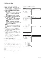
A004 : CAPSTAN FREE SPEED
This menu is used to perform the automatic adjustment of
a capstan free speed.
n
Adjust in 525/60 system.
To execute the automatic adjustment
n
Message “SET ALIGNMENT TAPE AND PUSH PLAY
KEY” is displayed on the LCD monitor when this menu is
opened. However, it is not necessary to press the PLAY
button.
(1) Insert an alignment tape CR2-1B.
.
The adjustment is initiated when an alignment tape
is inserted.
.
Message “ADJUSTING......” is displayed on only
the LCD monitor during automatic adjustment.
m
.
Be sure to use the specified alignment tape.
If the specified cassette tape is not used, the adjust-
ment cannot be properly performed even if message
“ADJUST COMPLETE” is displayed after it is
completed.
.
The tape amount on the portion that can be played
back after an alignment tape is inserted must exceed
the adjustment execution time.
The adjustment execution time is usually about 15
seconds.
(2) Confirm the adjustment result.
.
Message “ADJUST COMPLETE” is displayed on
the LCD monitor when the automatic adjustment is
completed normally.
An alignment tape is ejected automatically.
.
Message “# ADJUST INCOMPLETE #” is dis-
played on the LCD monitor when no adjustment
can be performed. The automatic adjustment is
then interrupted. Refer to the “For Automatic
Adjustment Failure” on page 2-16 when this
message is displayed.
(3) Press the MENU button to terminate the menu.
(4) To save the adjustment data in the NV-RAM of a
servo system, execute the SAVE SERVO ADJUST
data in an A006 : NV-RAM CONTROL menu.
Example of display and operation
2-2. TAPE Maintenance Mode (M0)
2-2-2. SERVO ADJUST Mode (A0)
Содержание BVW-55
Страница 1: ...VIDEOCASSETTE RECORDER BVW 55 MAINTENANCE MANUAL Part 1 1st Edition Serial No 10001 and Higher ...
Страница 4: ......
Страница 8: ......
Страница 50: ...1 40 BVW 55 1 2 3 4 5 6 7 8 9 d l s d l 1 15 Fixtures and Adjustment Equipment List ...
Страница 58: ......
Страница 106: ......
Страница 116: ......
Страница 130: ......
Страница 148: ......
Страница 150: ...Printed in Japan Sony Corporation 1999 3 08 Broadcasting Professional Systems Company 1999 BVW 55 UC E 3 202 213 01 1 ...
Страница 151: ...VIDEOCASSETTE RECORDER BVW 55 MAINTENANCE MANUAL Part 2 Volume 1 1st Edition Serial No 10001 and Higher ...
Страница 154: ......
Страница 158: ......
Страница 169: ...1 9 BVW 55 P2 1 2 Fixtures and Adjustment Equipment List 1 2 3 4 5 6 7 8 9 d l s d l ...
Страница 176: ......
Страница 272: ......
Страница 384: ......
Страница 386: ...Printed in Japan Sony Corporation 1999 7 08 Broadcasting Professional Systems Company 1999 BVW 55 UC E 9 967 828 01 ...
Страница 392: ......
Страница 396: ...1 2 BVW 55 ...
Страница 407: ...1 13 BVW 55 Bottom Side of Mechanical Deck 407 407 411 410 404 405 404 405 401 402 403 404 405 403 406 409 408 ...
Страница 666: ......
Страница 705: ......
Страница 752: ......
Страница 780: ......
Страница 805: ......
Страница 848: ......
Страница 856: ......
Страница 870: ......
Страница 884: ......
Страница 904: ......
Страница 909: ...5 27 b BVW 55 5 27 b CN101 CN301 CN302 CN303 CN901 MB 838 B SIDE SUFFIX 12 MB 838 MB 838 ...
Страница 911: ...5 27 a BVW 55 5 27 a CN101 CN301 CN302 CN303 CN901 MB 838 B SIDE SUFFIX 11 MB 838 MB 838 ...
Страница 940: ......
Страница 942: ...Printed in Japan Sony Corporation 1999 7 08 Broadcasting Professional Systems Company 1999 BVW 55 J UC J E 9 967 829 01 ...