4-3
FVS-1000 MMP1
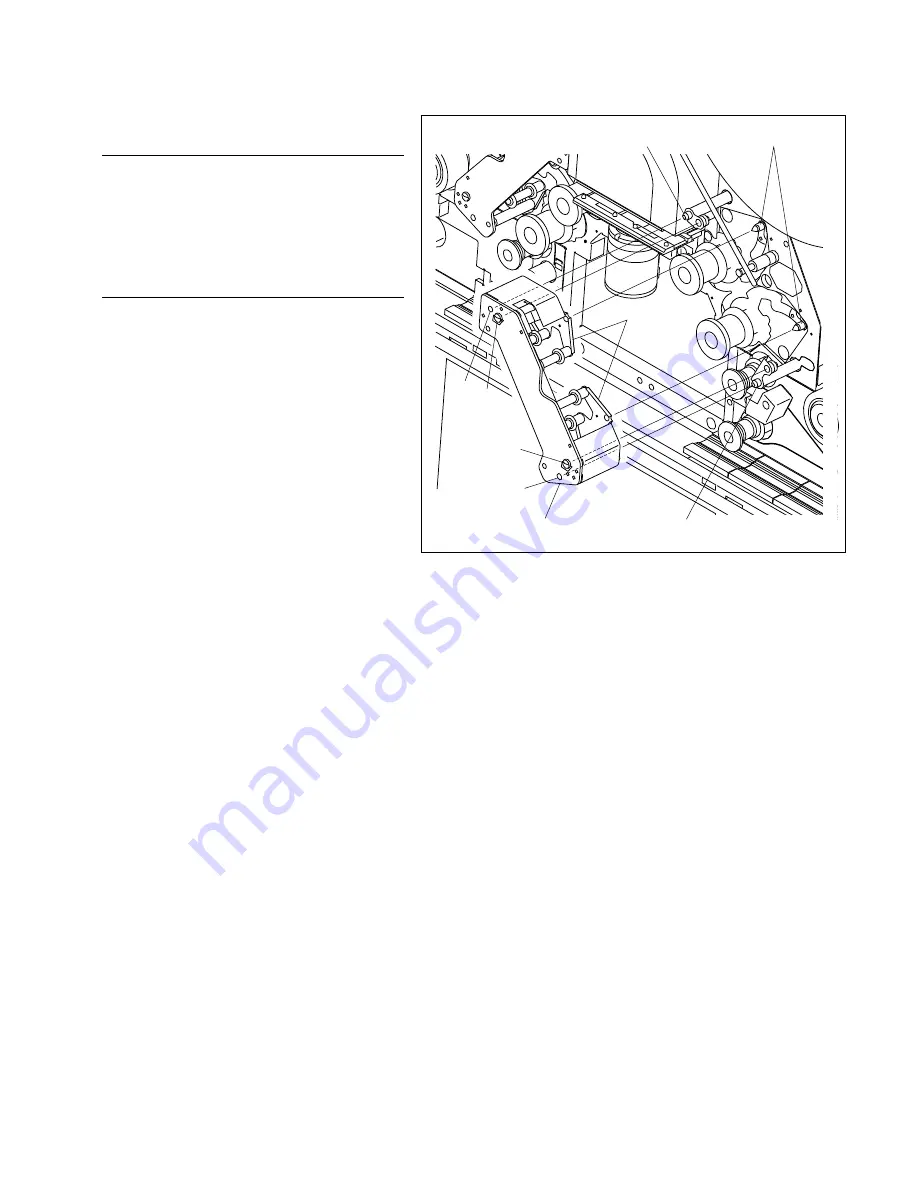
Pad driving pins
35T pad assembly
Reference hole
Slot
Pad arms
Pad positioning shaft
Pad positioning shaft
A
A
35T Pad Assembly
Removal
1. Removing the pad assembly
Rotate the two screws of the A portion with your
fingers in the counterclockwise direction, and
remove the 35T pad assembly.
Installation
2. Installing the pad assembly
(1) Align the reference hole and long hole of the
35T pad assembly and the pad positioning
shaft.
n
At this time, check that the pad drive pin
enters the slot of the pad arm.
(2) Press the 35T pad assembly against the base
plate, rotate the two screws of the A portion
with your fingers in the counterclockwise
direction, and install.
4-2. Replacing the Pad Assembly
Содержание BKFV-100
Страница 4: ......
Страница 8: ......
Страница 34: ......
Страница 38: ...2 4 FVS 1000 MMP1 2 3 Location of Main Parts FVS T1000 Rear panel 1 1 1 1 1 7 6 8 9 1 1 1 5 4 2 3 Rear side ...
Страница 44: ...2 10 FVS 1000 MMP1 2 3 4 Location of Sensors 2 3 Location of Main Parts Front side 4 5 6 8 8 9 7 0 3 2 1 ...
Страница 130: ...7 4 FVS 1000 MMP1 O A 8321 649 A FILTER ASSY BOX S 1 758 295 11 IR UV CUT FILTER S 1 517 872 11 LAMP WITH PLASTIC CASE ...
Страница 132: ......
Страница 136: ......


