1 (E)
BCU-100 MM
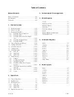
Table of Contents
Manual Structure
Purpose of this manual ........................................................... 3 (E)
Related manuals ..................................................................... 3 (E)
Trademarks ............................................................................. 3 (E)
1.
Service Overview
1-1.
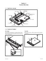
Main Parts Location ................................................. 1-1 (E)
1-2.
Removal of Cabinet ................................................. 1-1 (E)
1-3.
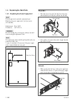
Replacing the Main Parts ......................................... 1-2 (E)
1-3-1.
Replacing the Power Supply Unit .................. 1-2 (E)
1-3-2.
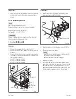
Replacing the Fan ........................................... 1-3 (E)
1-3-3.
Replacing the Fan for the Power Supply
Unit ................................................................. 1-5 (E)
1-3-4.
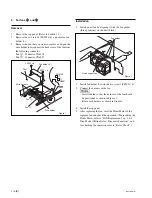
Replacing the Lithium Battery ....................... 1-5 (E)
1-3-5.
Replacing the HDD ........................................ 1-6 (E)
1-4.
Notes on Replacing the IC/Board ............................ 1-7 (E)
1-5.
Updating the Firmware ............................................ 1-8 (E)
1-6.
Circuit-Protection Part ........................................... 1-11 (E)
1-7.
Unleaded Solder ..................................................... 1-11 (E)
1-8.
Circuit Description ................................................. 1-12 (E)
1-8-1.
BCU-100 ...................................................... 1-12 (E)
1-8-2.
BKCU-EX1 .................................................. 1-16 (E)
1-8-3.
BKCU-VD1 .................................................. 1-17 (E)
1-9.
Troubleshooting ..................................................... 1-18 (E)
1-9-1.
Summary ...................................................... 1-18 (E)
1-9-2.
Self-diagnostic Function .............................. 1-19 (E)
1-9-3.
Troubleshooting Flow .................................. 1-20 (E)
1-9-4.
Diag Mode (Offline Defect Diagnosis
Function) ...................................................... 1-22 (E)
1-9-5.
Checking the Operation State with LED
Indication ...................................................... 1-39 (E)
1-9-6.
Error Code List ............................................. 1-43 (E)
1-9-7.
System .......................................................... 1-45 (E)
2.
Spare Parts
2-1.
Notes on Repair Parts ..................................................... 2-1
2-2.
Exploded Views .............................................................. 2-2
2-3.
Electrical Parts List ......................................................... 2-6
2-3-1.
BCU-100 ............................................................... 2-6
2-3-2.
BKCU-EX1 ......................................................... 2-45
2-3-3.
BKCU-VD1 ......................................................... 2-63
2-4.
Supplied Accessories List ............................................. 2-66
3.
Semiconductor Pin Assignments
4.
Block Diagrams
Overall ............................................................................ 4-1
BE-28 System Clock ....................................................... 4-2
BE-28 I2C Structure ....................................................... 4-3
BE-28 Reset .................................................................... 4-4
BE-28 Power Supply ...................................................... 4-5
RE-255 ............................................................................ 4-6
MEM-122/MEM-126 (BKCU-EX1) .............................. 4-6
VIF-40 (BKCU-VD1) ..................................................... 4-7
5.
Schematic Diagrams
BE-28 .............................................................................. 5-2
CN-3056 ....................................................................... 5-54
EX-1076 ........................................................................ 5-55
KY-631 ......................................................................... 5-56
LED-471 ....................................................................... 5-58
RE-255 .......................................................................... 5-59
MEM-122 ..................................................................... 5-60
MEM-126 ..................................................................... 5-67
VIF-40 ........................................................................... 5-74
Frame Wiring ................................................................ 5-82
6.
Board Layouts
BE-28 .............................................................................. 6-2
CN-3056 ......................................................................... 6-8
EX-1076 .......................................................................... 6-8
KY-631 ........................................................................... 6-8
LED-471 ......................................................................... 6-8
RE-255 ............................................................................ 6-9
MEM-122 ..................................................................... 6-10
MEM-126 ..................................................................... 6-12
VIF-40 ........................................................................... 6-14

