background image

16

D:\Cmeng's JOB\SONY TV\SY0265_W2\4273010311_LS\LS03STU.fm

KDL-EX727/EX725/EX527/EX525/EX427/EX425/CX527/CX525

4-273-010-

31

(1)

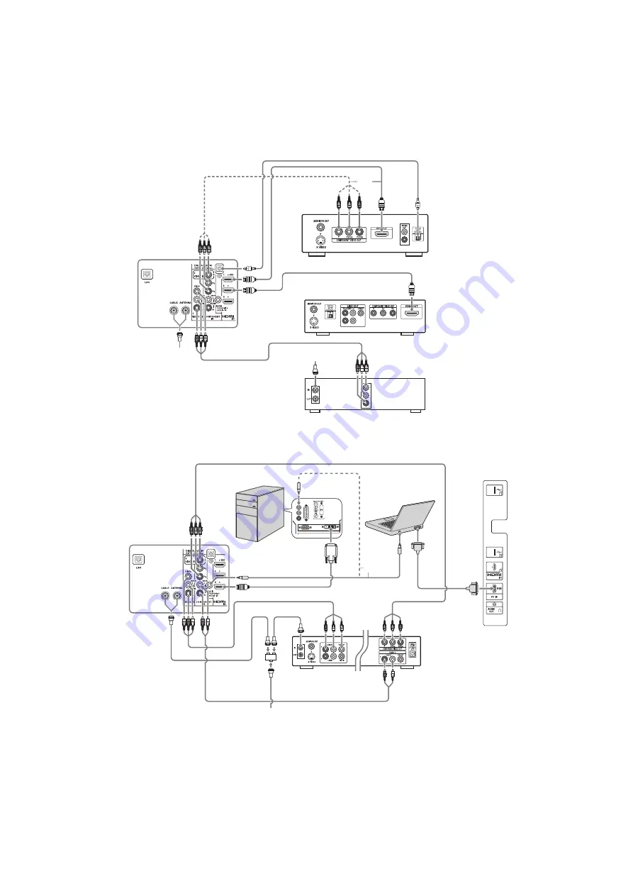
Se muestra con una conexión básica HD con un sistema de cine en casa

Se muestra con conexión de PC con VCR/DVD SD

Parte posterior 
del TV

Cable/
Antena

o

Blu-ray Disc/DVD

Decodificador de cable SD o 
Receptor satelital SD

Cable/SAT (Plato)

Sistema de cine en casa

*Conexión óptica

* La conexión óptica solo es necesaria para receptores de A/V que no soportan ARC.

Parte posterior 
del TV

Panel lateral

PC

DVD

VCR

Separador

Cable/Antena

Combinación de VCR/DVD

PC portátil

o

Содержание AZ2-F

Страница 1: ...Date Subject 1 0 2 2 2011 Original Manual Release Date 2 0 6 22 2011 Updated TOC Added VCOMAdjustments to Section 7 ServiceAdjustments Replaced and or added pages 53 58 3 0 12 21 2011 Reissue entire manual ORIGINAL MANUAL ISSUE DATE 1 2011 HISTORY INFORMATION FOR THE FOLLOWING MANUAL ...

Страница 2: ...SERVICE MANUAL LCD Digital Color TV AZ2 F Chassis Segment P 1 9 888 394 03 SelfDiagnosis Supported model KDL 32EX427 ...

Страница 3: ...MODEL LIST MODEL COMMANDER DESTINATION MODEL COMMANDER DESTINATION KDL 32EX427 RM YD064 COLUMBIA KDL 32EX527 RM YD064 COLUMBIA KDL 40EX527 RM YD064 COLUMBIA KDL 46EX527 RM YD064 COLUMBIA 9 888 394 03 ...

Страница 4: ...Videos Music 10 Specifications 11 Section 2 Software Requirements 12 Overview 12 Software Updates for Customers 12 Software Updates for Servicers 13 Software Update Responsibility 13 Checking the Software Version 13 Examples of Software Correctable Symptoms 14 Section 3 Chassis Overview 15 Overview 15 Overall Circuit Descriptions 17 Main Board 17 Tuner 17 X Reality Processor 17 Audio Amplifier 17 ...

Страница 5: ... Screw Legend 50 Connectors 50 Accessories and Packaging 51 Miscellaneous 51 Optional Accessories 51 Remote Commander 51 Wire Dressing 52 Section 7 Service Adjustments 53 Overview 53 Updating the Software 53 Accessing Service Adjustment Mode 53 Viewing or Changing Service Data 54 Updating Service Adjustment Data When Replacing the Main Board 55 Selecting the Segment Code 55 Selecting the Destinati...

Страница 6: ...Removing the Power Cord from the Rear Cover A 1 KDL 32EX427 32EX527 Only A 1 KDL 40EX527 Only A 3 KDL 46EX527 Only A 5 Appendix B Attaching the Rear Cover B 1 Reattaching the Rear Cover to the Bezel B 1 KDL 32EX427 32EX527 Only B 1 KDL 40EX527 Only B 2 KDL 46EX527 Only B 2 Appendix C Replacing the LCD Panel C 1 Removing the LCD Panel from the Bezel C 1 Reattaching the LCD Panel onto the Bezel C 2 ...

Страница 7: ...ve chassis The chassis of this receiver is directly connected to the AC power line SAFETY RELATED COMPONENT WARNING Components identified by shading and mark on the exploded views are critical for safe operation Replace all components with Sony parts whose part numbers appear as shown in this manual or in supplements published by Sony It is essential that all critical parts be replaced only with t...

Страница 8: ...spray water or detergent directly onto the TV screen If liquid drips into the bottom of the screen it may cause a failure CLEANING THE LCD PANEL CAUTION When cleaning the TV be sure to unplug the power cord to avoid any chance of electric shock Clean the cabinet of the TV with a dry soft cloth Wipe the LCD screen gently with a soft cloth R Stubborn stains may be removed with a cloth slightly moist...

Страница 9: ...FC Connector pull out the connector while continuing to hold down the release tab of the Main Board connector Connector Type 1 1 Slightly tilt the Main Board connector release away from the LVDS FFC Connector DO NOT remove the LVDS FFC Connector by the reinforcement tab only 2 Gently wiggle the LVDS FFC Connector to detach it from the Main Board 䐠 Main Board Reinforcement Tab Tilt away from LVDS 䐠...

Страница 10: ...tor 2 Holding onto the entire LVDS FFC Connector insert the LVDS FFC Connector into the Main Board connector Connector Type 1 1 While holding onto the LVDS FFC Connector gently tilt the Main Board connector release towards the Main Board then slide the LVDS FFC Connector straight in Main Board Reinforcement Tab Tilt away from LVDS Main Board Reinforcement Tab Press down 䐠 Connector Type 3 1 Gently...

Страница 11: ...dule in high temperatures or in areas of high humidity for an extended period of time 4 Do not expose the LCD panel to direct sunlight 5 Avoid contact with water It may cause a short circuit within the module 6 Disconnect the AC power when replacing the backlight or inverter circuit High voltage occurs at the inverter circuit at 650Vrms 7 Always clean the LCD panel with a soft cloth material 8 Use...

Страница 12: ...rs ground straps and mounting hardware have been replaced Be absolutely certain that you have replaced all the insulators 4 Look for unauthorized replacement parts particularly transistors that were installed during a previous repair Point them out to the customer and recommend their replacement 5 Look for parts which though functioning show obvious signs of deterioration Point them out to the cus...

Страница 13: ...ndication is 0 75V so analog meters must have an accurate low voltage scale The Simpson s 250 and Sanwa SH 63TRD are examples of passive VOMs that are suitable Nearly all battery operated digital multimeters that have a 2 VAC range are suitable see Figure A HOW TO FIND A GOOD EARTH GROUND The cover plate retaining screw on most AC outlet boxes is at earth ground Verify the AC outlet box retaining ...

Страница 14: ... translates to a probable source of the problem A definition of the STANDBY LED flash indicator is listed in the Operating Instruction manual for the user s reference If an error symptom cannot be reproduced the remote commander can be used to review the failure occurrence data stored in memory to reveal past problems and how often these problems occur For complete information refer to Section 4 T...

Страница 15: ...ately 2 Integrated Wi Fi Conveniently stream entertainment straight from the Internet and from your home network using the built in Wi Fi 1 DLNA Streaming Access and share photos videos and music on your TV by streaming them from compatible DLNA device like your PC or Playstation 3 system 3 FASTER START UP Quick Start Viewing feature enables this Sony television to go from OFF to ON 2 3 times fast...

Страница 16: ...e energy without lifting a finger The built in Light Sensor automatically adjusts the picture brightness based on the amount of light in the room PRESENCE SENSOR Save energy when you re not around The television s built in motion sensor has the ability to scan the room and detect movement If the sensor detects no movement it automatically turns off the picture leaving only sound After more time an...

Страница 17: ...io aviso Nombre del modelo KDL 32EX527 32EX427 Alimentación y otras especificaciones Requisitos de alimentación 110 240 V ca 50 60 Hz Consumo energético 103 W 102 W 77 W en uso en espera Menos de 0 25 W Menos de 0 3 W Tamaño de pantalla cm medido diagonalmente pulgadas 46 80 1 31 5 32 clase 80 0 31 5 32 clase Resolución del monitor 1 920 puntos horizontal 1 080 líneas vertical 1 366 puntos horizon...

Страница 18: ...n the home Some examples are Portable audio and video devices still cameras home computer networks and accessing the internet to name a few Communications with these varying devices requires that the television be compatible with varying communications protocols Although standards are detailed for each of these protocols the real world dictates that occasional errors may occur that could prevent d...

Страница 19: ...on service adjustment information may need to be modified or verified to complete the service of the TV Service adjustment information is covered in Section 7 Service Adjustments on page 53 SOFTWARE UPDATE RESPONSIBILITY Software updates are designed to be performed by the customer Warranty repairs in which the issue can be resolved by a software update are not reimbursable Most issues involving s...

Страница 20: ... of some of the symptoms that may be corrected with a software update Fluctuations in picture brightness Intermittent picture freezing or noise Problems with certain inputs especially HDMI Intermittent or distorted audio Erratic remote control operation Unit turns on and off by itself Loss of color Internet connectivity Certain features not working correctly photo or video file viewing Loss of col...

Страница 21: ...rd for the 40 46 the Motion Sensor HMS3 Board the IR Board HLR2 Board the Switch Unit and the LCD Panel Assembly which includes the TCON Board NOTE For connector part number information refer to Connectors on page 50 For Wire Dressing information refer to Wire Dressing on page 52 SWITCH UNIT HLR2 HMS3 GE2 TCON BATV Figure 3 1 BOARD LAYOUT FOR KDL 32EX427 32EX527 SECTION 3 CHASSIS OVERVIEW ...

Страница 22: ...427 32EX527 40EX527 46EX527 16 SECTION 3 CHASSIS OVERVIEW SWITCH UNIT HLR2 HMS3 GE3 TCON BATV Figure 3 2 BOARD LAYOUT FOR KDL 40EX527 SWITCH UNIT HLR2 HMS3 GE3 TCON BATV Figure 3 3 BOARD LAYOUT FOR KDL 46EX527 ...

Страница 23: ...received from the tuner for decompression All video sources which are not native 1920 X 1080p 60HZ are scaled to this resolution Digital audio content is output to the class D amplifier for processing and amplification HDMI Input and Switching HDMI inputs are switched through IC5500 Each HDMI input contains a common EDID NVM internal to IC5500 to provide display information data to any device conn...

Страница 24: ...ensor detects when there is movement in front of the TV If there is no movement in front of the TV after a predetermine amount of time the backlight is turned off audio present After an extended period of time the TV is completely turned off IR BOARD Designated as the HLR2 Board the IR Board contains the power standby and timer LED s are located on this board along with the IR remote receiver and ...

Страница 25: ...ol LVDS Keys Power SIRCS LCD Panel Assembly LCD PANEL Power Key Function Keys Switch Unit LEDs IR Sensor Light Level HLR2 Board Power Main Power Supply Standby Power Supply AC Relay LED Backlight Power Supplies GE2 Board 32 GE3 Board 40 46 LCD Panel R L RF Input Component Composite PC Input 4 HDMI Inputs Optical Digital Audio Output LED Backlight System TCON HFR Power AC Input 2 USB 2 0 Motion Sen...

Страница 26: ... Sensor SIRCS I2CA X_Hotel_PWR_CTRL I2CA EQSW Temp Sensor Hotel Clock I2CB Ext Demod I2CC Panel RGB Sensor UARTA LOG UARTB RF Remote UARTC IR Blaster ECS KEY Light Sensor Human Sensor LED Light_Sensor_Det Human_Sensor_Det STBY_LED POWER_LED TIMER_LED PIC_MUTE_LED REC_LED Power_KEY KEY UARTE DIMMER DMD_CLK_ENABLE2 DIMMER_DC LOGO DEBUG_LED2 DEBUG_LED3 PANEL_PWR DMD_CLK_ENABLE1 DMD_RST X_WIFI_RST HP_...

Страница 27: ... 842 088 11 1 33 HLR STBY_3 3V V 3 3 R L H 4 3 1 1 5 1 1 C N Y S Y E K _ R E W O P W S 5 3 2 6 1 2 T E S E R Y E K _ W S 6 3 3 7 1 3 D N G e l u d o m C R F R D N G W S 7 3 1 3 1 4 X R 1 P 2 a 3 1 a 3 3 b 2 2 b 2 1 b 2 O G O L Y N O S T E D S M H 8 3 2 4 1 5 X T n a p a J y l n o V 5 O G O L V 5 S M H 9 3 3 2 1 6 D D V JAM SYT10 06 WL ET 1 40 HMS GND LOGO GND 1 821 146 11 CN9006 1 818 692 21 1 JST...

Страница 28: ... N G 6 1 6 3 D N G Y E K W S 6 3 3 W I FIVC C 2 23 P 2 D D O L E N A P 5 1 7 3 P 2 D D O L E N A P D N G W S 7 3 1 C N 9 1 3 P B S U I F I W N 2 D D O L E N A P 4 1 8 3 N 2 D D O L E N A P O G O L Y N O S T E D S M H 8 3 2 C N 1 2 4 M B S U I F I W P 1 D D O L E N A P 3 1 9 3 P 1 D D O L E N A P V 5 O G O L V 5 S M H 9 3 3 C N 8 1 5 D N G I F I W N 1 D D O L E N A P 2 1 0 4 N 1 D D O L E N A P D N...

Страница 29: ... TVs UPDATING THE SOFTWARE Asmentionedin Section2 SoftwareRequirements onpage12there are several issues that may be resloved by updating the software to the latest version For a list of possible correctable issues see Examples of Software Correctable Symptoms on page 14 SECTION 4 TROUBLESHOOTING SelfDiagnosis Supported model ...

Страница 30: ...ides to isolate the board RED DOT Most likely defective part LAST UPDATED 6 9 2011 Remote Audio 2 3 4 5 6 7 8 Green LED Blinking Constantly ON OFF Cycling Green LED Constant ON No Green Power LED Dead Set No video Whole Screen Distortion Isolated area Distortion No Remote No Audio MAIN BOARD POWER BOARD HLR2 BOARD Service Bulletin Software Update TCON Board LCD Panel Problem POWER AUDIO POWER BACK...

Страница 31: ...e or circuit caused the protection event Not all of the available protect codes are used in every model For example models that are LED backlit do not use the 4 blink balancer error as this circuit is found in models that are backlit with fluorescent lamps The following list contains the protect circuits and diagnostics codes used in the models listed in this manual Figure 4 3 Diagnostic Table on ...

Страница 32: ...f the TCON is not available the LCD panel must be replaced since the TCON circuit is part of the LCD panel assembly In rare cases a loose or defective LVDS cable could also be the cause 6X Blink Backlight System Failure If the inverter circuits fails to generate high voltage or one or more of the backlight lamps fails to light the television will shut down and display this diagnostics error Observ...

Страница 33: ...OWER Main Power Error 2 GE2 Power Board KDL 32EX427 32EX527 Models GE3 Power Board KDL 40EX527 46EX527 Models DC_ALERT DC Regulator Audio Error AUD_PROT Audio Error Detection BALANCER Balancer Error 4 BATV Board TCON ERR TCON Error P_ID_ERR Panel ID NVM Error BACKLITE Backlight Error 6 BATV Board TEMP_ERR Temperature Error 7 Ventilation BATV Board 103 HOST_WDT Watch Dog Timer Notification 8 Servic...

Страница 34: ...MITTER 00 007 FAN_ERR 00 012 IA 00 SELF CHECK StandBy LED Flash Count Diagnostic Item Error Count 00 99 00 00 101 VPC_WDT 00 102 MEPS_WDT 00 103 HOST_WDT 00 104 STBY_WDT 00 000 RGB_SEN 000 RESERVED 000 RESERVED Figure 4 4 SAMPLE SELF CHECK DIAGNOSIS PAGE CLEARING THE SELF CHECK DIAGNOSTIC LIST Since the diagnostic results displayed on the screen are not automatically cleared always check the self ...

Страница 35: ... a solution START Does the Power Led stay on when the TV is switched on Is the Standby Led blinking Is the Picture and Sound OK END See No Power See Standby LED Blinking See No Picture or No Sound Is the network connection OK See Network Not Connecting No Yes Yes No Yes Do the buttons on the TV Remote Commander work properly See TV Remote Commander Buttons Not Working No No Yes No Yes No See Skype...

Страница 36: ...40EX527 46EX527 30 SECTION 5 FLOW CHARTS AND DIAGRAMS NO POWER No Power Check STBY 3 3V at 10 pin of CN6001 on the B Board Harness G Board Replace Harness Between G Board and B Board B Board NG OK NG OK Figure 5 2 NO POWER ...

Страница 37: ...527 31 SECTION 5 FLOW CHARTS AND DIAGRAMS STANDBY LED BLINKING 2X Blink Check REG12V at pins 2 3 of CN6001 on the B Board B Board Harness G Board Replace Harness between G Board and B Board 12V NG 12V OK NG OK Figure 5 3 2 BLINK ERROR ...

Страница 38: ... Board Speaker Check 3 3V_MAIN at JL9234 on the B Board Check Speaker Connector F6003 IC6003 etc B Board Check AUDIO 12 5V at pin 8 9 of CN6001 on the B Board G Board Check 12 5V at F4601 on the B Board F4601 IC4601 etc B Board IC4601 etc B Board DC_ALERT NG OK AUDIO AUDIO FE BE Communication NG OK NG OK NG OK NG OK Figure 5 4 3 BLINK ERROR ...

Страница 39: ...f CN6001 on on the B Board G Board Replace the Harness between G and LCD PANEL a Replace the LVDS Connector LCD PANEL T con change B Board Harness LVDS Connector TCON LCD PANEL a exclude 60Hz LCD PANEL Model 12V NG 12V OK NG Symptom improvement Symptom improvement Symptom improvement NG NG Figure 5 5 5 BLINK ERROR ...

Страница 40: ...40EX527 46EX527 34 SECTION 5 FLOW CHARTS AND DIAGRAMS 6X Blink Check BL_ERR at pin 7 of CN6002 on the B Board B Board Under 2 65V G board NG Over 2 65V Symptom improvement Change G Board LCD PANEL Figure 5 6 6 BLINK ERROR ...

Страница 41: ...32EX527 40EX527 46EX527 35 SECTION 5 FLOW CHARTS AND DIAGRAMS 7X Blink Setting is OK Check Temperature and Ventilation Set to another Location etc NO YES Change B Board B Board OK LCD PANEL Figure 5 7 7 BLINK ERROR ...

Страница 42: ...EX527 36 SECTION 5 FLOW CHARTS AND DIAGRAMS POWER LED Green blinking OK LCD PANEL NG Check LCD PANEL Check the harness between the G Board and LCD PANEL Harness NG OK Check G Board B Board OK G Board NG Figure 5 8 POWER LED BLINKING ...

Страница 43: ...d B Board Replace the LVDS Harness LCD PANEL TCON Harness LVDS Check BL_ON at JL6018 on the B Board BL_ON H B Board Replace Harness between G Board to B Board Harness G Board to B Board BL_ON L Change B Board G Board NO YES NG OK NG OK NG OK LCD PANEL_VCC At JL6004 on the B Board G Board 12V OK 12V NG Figure 5 9 NO PICTURE ERROR ...

Страница 44: ... SECTION 5 FLOW CHARTS AND DIAGRAMS NO SOUND No Sound Check the Speaker Harness Speaker Harness Replace the B Board B Board Speaker OK NG NG OK Check the Speakers setting Change to TV Speaker Audio System TV Speakers Figure 5 10 AUDIO ERROR ...

Страница 45: ...ECTION 5 FLOW CHARTS AND DIAGRAMS TV REMOTE COMMANDER BUTTONS NOT WORKING TV POWER Button not working Replace the Harness between B to Switch Unit Switch Unit Harness Switch Unit change B Board OK NG OK NG Figure 5 11 TV BUTTONS MALFUCTIONING ...

Страница 46: ...ight at power indicator OK NG Sensor is broken HLR Board B Board OK NG Mechanical ex bezel Green LED blinks at power indicator when using commander near sensor s window Check the Harness between the B Board and the HLR Board Exchange the Harness Exchange the HLR Board Harness OK NG OK OK NG NG Figure 5 12 IR MALFUCTIONING ...

Страница 47: ...on the TV Check Local Access Check Cable Connection OK NG OK NG Check Internet Access Proxy setting NG B Board Check Ethernet Cable Ethernet Cable Check IP address and Local router setting Wired Set up IP address setting Check Local router DHCP server Auto Manual OK NG Figure 5 13 WIRELESS NETWORK MALFUCTIONING ...

Страница 48: ...OW CHARTS AND DIAGRAMS Wireless Network on the TV Is the signal field strength too weak or is there No signal Access Point B Board Error Message displays when the Wireless Network is selected USB Dongle NO YES NO YES Figure 5 14 USB DEVICE MALFUCTIONONG ...

Страница 49: ...USB plugged in Insert USB Able to run Skype App Spec USB overload Connect to a different USB port B board Insert another Skype unit or USB dongle Skype unit B board Network connected Reset network Yes No Yes No No OK NG OK NG OK NG Next page Yes Unplug another USB device AC OFF ON Figure 5 15 SKYPE NOT WORKING PROPERLY PAGE 1 OF 2 ...

Страница 50: ...tem issue Auto Focus work Sound quality No video Manual Focus work Check Auto Focus area Enough network speed Skype unit Call Skype sound test Far end setting system Move unit away from speaker Skype unit Audio problem Video problem Previous page OK NG Yes No Yes No No Yes Yes NG Figure 5 16 SKYPE NOT WORKING PROPERLY PAGE 2 OF 2 ...

Страница 51: ...NO DESCRIPTION ASSEMBLY INCLUDES REF NO PART NO DESCRIPTION ASSEMBLY INCLUDES 1 4 268 538 01 STAND HEAD P M KDL 32EX427 32EX527 ONLY 1 4 268 539 01 STAND HEAD P ML KDL 40EX527 ONLY 1 4 267 497 01 STAND HEAD ML9 KDL 46EX527 ONLY 2 4 268 542 01 STAND NECK P M KDL 32EX427 32EX527 ONLY 2 4 268 543 01 STAND NECK P ML KDL 40EX527 ONLY 2 4 259 183 02 NECK L9 KDL 46EX527 ONLY 3 4 268 548 01 STAND PIPE M K...

Страница 52: ...n page A 1 for complete instructions A Remove screws from Rear Cover 5 from KDL 32EX427 32EX527 Only 4 from KDL 40EX527 Only 6 from KDL 46EX527 Only B Remove 1 screw from Terminal Area position C Remove 2 screws from Rear Cover D Remove 1 screw and release clips from AC Cover to detach from Rear Cover Refer to Removing the Power Cord from the Rear Cover on page A 1 E Remove 2 screws from Rear Cove...

Страница 53: ... side Speaker KDL 46EX527Only H Slide out left side Speaker to detach from Bezel I Release 2 clips to detach Side Jack Bracket from BATV Board J Gently peel off Side Jack Label to detach from LCD Panel Note The Side Jack Label is not included with the LCD Panel and must be replaced when replacing the LCD Panel 101 1 474 277 12 GE2A BOARD COMPLETE KDL 32EX427 32EX527 ONLY 101 1 474 287 11 GE3A BOAR...

Страница 54: ...r to Handling the LVDS FFC Connector on page 3 C Gently peel off Insulation Sheet to detach from LCD Panel D Remove 1 screw from HMS3 Board E Release clips and disconnect 1 connector to detach HMS3 Board from LED Guide F Lift up the Frenel Lens to detach from LED Guide G Release clips and disconnect 1 connector to detach HLR2 Board from LED Guide 152 4 268 446 01 SHEET INSULATION G10 KDL 32EX427 3...

Страница 55: ...el Bracket H from top side to detach from Bezel B Lift up Panel Bracket C from right and left side to detach from Bezel 3 from KDL 32EX427 32EX527 Only 4 from KDL 40EX527 Only 6 from KDL 46EX527 Only C Gently lift up LCD Panel to detach from Bezel 202 NA LCD PANEL FOR ALL LCD PANELAND TCON PART NUMBER INFORMATION REFER TO THE LCD PANELS SERVICE MANUAL 203 4 266 012 01 BRACKET PANEL C 204 4 266 016...

Страница 56: ... 580 608 01 SCREW PSW M5X16 TABLE TOP STAND 3 3 4 256 393 01 SCREW PSW M3X6 W12 RC 5 AC COVER 1 6 7 685 648 79 SCREW BVTP 3X12 TYPE2 IT 3 RC to TERMINAL AREA 1 1 2 580 639 01 SCREW BVTP 4X12 TYPE2 IT 3 RC 7 7 4 257 907 01 JOINT STAND RC 2 2 4 268 126 02 SCREW ORNAMENTAL M6X12 RC 2 2 2 990 421 41 SCREW PSW M3X6 BATV 5 GE2A 5 10 7 685 646 79 SCREW BVTP 3X8 TYPE2 IT 3 HMS3 1 1 4 167 964 01 SCREW PWTP...

Страница 57: ...ST SCREWS TO ATTACH NECK TO HEAD STAND AND BASE STAND 3 299 071 05 FLYER SAFETY 4 273 074 11 FLYER SAFETY 4 273 010 31 MANUAL INSTRUCTION 1 838 797 11 POWER SUPPLY CORD WITH CONN 4 159 298 01 SCREW PSW M4X10 KDL 32EX427 32EX527 40EX527 ONLY 4 270 904 11 SUPPLEMENT STAND INSTALLATION KDL 46EX527 ONLY MISCELLANEOUS 4 262 708 01 CLAMPER CABLE 4 272 200 01 DOUBLE SIDED TAPE PANEL ORDER THIS PART WHEN ...

Страница 58: ...40EX527 46EX527 52 SECTION 6 DISASSEMBLY PART NUMBER INFORMATION WIRE DRESSING Figure 6 1 KDL 32EX427 32EX527 OVERALL WIRE DRESSING Figure 6 2 KDL 40EX527 OVERALL WIRE DRESSING Figure 6 3 KDL 46EX527 OVERALL WIRE DRESSING ...

Страница 59: ...anged or confirmed when either the main Board LCD Panel or TCON Board are replaced UPDATING THE SOFTWARE After replacing the main Board LCD Panel or TCON Board you MUST UPDATE the SOFTWARE to the latest version ACCESSING SERVICE ADJUSTMENT MODE 1 TV must be in standby mode Power off 2 Access Service Mode by pressing the following buttons on the Remote Commander within a second of each other DISPLA...

Страница 60: ...ISE_TH 32 Figure 7 2 SAMPLE CHASSIS SERVICE MENU VIEWING OR CHANGING SERVICE DATA Within each Service Menu are Categories and data information CHASSIS SERVICE 000 000 WYVERN S2_NOISE_TH 32 Data Value Item Name Category Number Item Number Category Name Figure 7 3 SERVICE DATA DEFINITIONS Use the buttons on the Remote Commander to review or change the service data 4 To change the Category press 2 to...

Страница 61: ...ELECTING THE SEGMENT CODE Before proceeding update the software to the latest version After updating the software go into Service Mode to select the correct Segment Code data value 1 TV must be in standby mode Power off 2 Access Service Mode by pressing the following buttons on the Remote Commander within a second of each other DISPLAY Channel 5 Volume POWER DIGITAL SERVICE 001 OP 000 VERS MAIN EX...

Страница 62: ...creen briefly indicates the process is Done DIGITAL SERVICE 002 MODEL 000 SEG I1 DONE 6 Exit service mode by pressing HOME and then turn the TV power off 7 Cycle AC Power Unplug and Plug AC Cord from the AC Outlet 8 Wait a minute while lights flash and initial setup screen shows 9 Proceed to Selecting the Destination SELECTING THE DESTINATION The correct destination needs to be selected after repl...

Страница 63: ...46LUX PD1 011J46LUX 3 Press 2 to move to the 002 MODEL category 4 Press 1 to move to the 001 DEST item DIGITAL SERVICE 002 MODEL 001 DEST LTN DVB 5 Using the table press 3 to increase the data value or 6 to decrease the data value to select the correct destination of the TV Model Name Destination Data Value KDL 32EX527 CO LTN DVB KDL 40EX527 CO LTN DVB KDL 46EX527 CO LTN DVB CAUTION Verify the DES...

Страница 64: ...ing to the next step Selected the Segment Code Selected the Destination 8 Press 1 to move to the 002 MODEL item DIGITAL SERVICE 002 MODEL 002 MODELNAME KDL 40EX527 9 If the correct model does not display press 3 until the model displayed matches the model of the TV 10 Press MUTING then press 0 to WRITE Save the changes DIGITAL SERVICE 002 MODEL 002 MODELNAME KDL 40EX527 WRITE When complete the scr...

Страница 65: ..._Trans press 3 to increase the data value to 1 VPC SERVICE 000 000 DATA_COPY BU_TRANS 1 NOTE If the message displays DATA TRANSFER NG the transfer is not complete If that occurs repeat step 13 VPC SERVICE 000 000 DATA_COPY BU_TRANS 2 DATA TRANSFER NG If successful the data value changes to 3 VPC SERVICE 000 000 DATA_COPY BU_TRANS 3 DATA TRANSFER SUCCESS 14 Verify the Data Transfer Success message ...

Страница 66: ...ITAL menu displays DIGITAL SERVICE 001 OP 000 VERS MAIN EXT DM1 301W00AA RF 01 05 WF1 003W00AA WF 2 0 0 99 DF1 001W00AA WF 0B YM1 010W00AA CAN X XXX DB2 105W00AA FDlXXXX DM1 301W00A DD1 016W00AA WP0 521W00AA PEM MID 1D95E756 PM1 012W00LU PID 10080000 PB1 000W00LU PNL LTY460HN0202 POP X XXX PL1 011J46LUX PD1 011J46LUX 18 Press 2 to move to the 002 MODEL category DIGITAL SERVICE 002 MODEL 000 SEG I1...

Страница 67: ...ial number 23 Press the select button to WRITE Save the serial number to the replacement Main Board DIGITAL MODEL SERVICE SerialNumberEdit 1 SerialNumber Please input serial number 0000000 9999999 3001318 WRITE When complete the screen indicates the process is Done then the serial number displays DIGITAL MODEL SERVICE DONE SerialNumberEdit 1 SerialNumber 3001318 24 Proceed to Confirming the Model ...

Страница 68: ...5E726 10080000 KDL 40EX527 CO T400HW04 V0 1D95E727 10080000 KDL 40EX527 CO V400HJ2 LE1 1D95E751 10080000 KDL 40EX527 CO LTY400HM0801 1D95E759 10080000 KDL 40EX527 CO T400HW05 V0 1D95E75C 10080000 KDL 46EX527 CO LTY460HN0201 1D95E725 10080000 KDL 46EX527 CO V460H3 LE2 1D95E750 10080000 KDL 46EX527 CO LTY460HN0202 1D95E756 10080000 DIGITAL SERVICE 001 OP 000 VERS MAIN EXT DM1 301W00AA RF 01 05 WF1 0...

Страница 69: ...om the TCON Board to the Main Board The BU Flash service item is under the VPC service menu 1 TV must be in standby mode Power off 2 Access Service Mode by pressing the following buttons on the Remote Commander within a second of each other DISPLAY Channel 5 Volume POWER DIGITAL SERVICE 001 OP 000 VERS MAIN EXT DM1 301W00AA RF 01 05 WF1 003W00AA WF 2 0 0 99 DF1 001W00AA WF 0B YM1 010W00AA CAN X XX...

Страница 70: ...s repeat step 5 VPC SERVICE 001 000 DATA_BAKUP BU_FLASH 2 DATA TRANSFER NG If successful the data value changes to 3 VPC SERVICE 001 000 DATA_BAKUP BU_FLASH 3 DATA TRANSFER SUCCESS 6 Verify the Data Transfer Success message displays 7 Proceed to Confirming the Model ID and Product ID CONFIRMING THE MODEL ID AND PRODUCT ID After completing all of the service adjustment changes verify that the corre...

Страница 71: ...0EX527 CO LTY400HM0801 1D95E759 10080000 KDL 40EX527 CO T400HW05 V0 1D95E75C 10080000 KDL 46EX527 CO LTY460HN0201 1D95E725 10080000 KDL 46EX527 CO V460H3 LE2 1D95E750 10080000 KDL 46EX527 CO LTY460HN0202 1D95E756 10080000 DIGITAL SERVICE 001 OP 000 VERS MAIN EXT DM1 301W00AA RF 01 05 WF1 003W00AA WF 2 0 0 99 DF1 001W00AA WF 0B YM1 010W00AA CAN X XXX DB2 105W00AA FDlXXXX DM1 301W00A DD1 016W00AA WP...

Страница 72: ...LF CHECK 00 00 101 VPC_WDT 00 102 MEPS_WDT 00 103 HOST_WDT 00 104 STBY_WDT 00 000 RGB_SEN 000 RESERVED 000 RESERVED 3 To clear the LCD Panel operating hours of the LCD Panel after replacing the panel press 7 0 Panel operation time Panel operation time 01 00 00 00 00 00 002 MAIN_POWE 003 DC_ALERT 003 AUD_PROT 004 BALANCER 005 HFR_ERR 005 P_ID_ERR 12345 00333 06789 12345 00333 00000 00 006 VLED 00 0...

Страница 73: ...SERVICE 003 DIG_SERV_MODE 000 TEST_PATTERN 4 Press 0 to display the TEST PATTERN DIGITAL DIG_SERV_MODE SERVICE TEST PATTERN 1 VIDEO 2 AUDIO 5 Press ENTER to display 1 Video DIGITAL DIG_SERV_MODE SERVICE TEST PATTERN 1 VIDEO 1 White 2 Ramp 3 R Raster 4 G Raster 5 B Raster 6 Color Bar 7 VCOM Adjustment1 8 VCOM Adjustment2 9 Off 6 Chose one of the VCOM test patterns to determine which one displays th...

Страница 74: ...ta value until the flickering in the picture is at an acceptable level VERIFYING THE VCOM ADJUSTMENT SETTINGS 14 Press JUMP to access the DIGITAL Service Menu 15 Press 2 to move to 007 VCOM category DIGITAL SERVICE 007 VCOM 000 SRV_OSD_EN 1 16 Press 3 to remove the on menu display 17 Verify that flickering is at an acceptable level NOTE If the picture continues to flickers repeat steps 8 thru 17 u...

Страница 75: ...1 010W00AA CAN X XXX DB2 105W00AA FDlXXXX DM1 301W00A DD1 016W00AA WP0 521W00AA PEM MID 1D95E756 PM1 012W00LU PID 10080000 PB1 000W00LU PNL LTY460HN0202 POP X XXX PL1 011J46LUX PD1 011J46LUX 3 Press JUMP or OPTIONS on the Remote Commander until the VPC menu displays VPC SERVICE 000 000 DATA_COPY BU_TRANS 0 4 Press 2 to move to 006 WB Category VPC SERVICE 006 000 WB R_DRV 128 5 To change the data v...

Страница 76: ... standby Mode POWER off 2 Press the following buttons on the Remote Commander within a second of each other DISPLAY Channel 5 Volume POWER If necessary press JUMP or OPTIONS to go to DIGITAL mode 3 Press the following buttons on the Remote Commander within a second of each other Press 8 MUTING 0 SERVICE changes to green RST RST executes the command and displays EXE EXE RST displays green then red ...

Страница 77: ... Sony Technology Center Technical Services Service Publication Department 9 888 394 03 English 2011BJ74WEB 1 Printed in USA 2011 2 is a trademark of Sony Electronics Reproduction in whole or part without written permission is prohibited All rights reserved ...

Страница 78: ... avoid pulling the AC Power Cord which may damage the cord Caution These instructions should be followed whenever removing the Rear Cover KDL 32EX427 32EX527 ONLY 1 Using the instructions provided in the Rear Cover and AC Cover Removal on page 46 remove the screws from the Rear Cover 2 Remove 1 screw from AC Cover 3 Using the illustration to locate the clips that secure the Rear Cover to the Bezel...

Страница 79: ...he Bezel 5 Continue pulling the Rear Cover up from the Bezel one section at a time 6 Lift up Rear Cover with AC Cover and AC Power Cord attached NOTE Hold AC Power Cord while lifting up Rear Cover Do not pull the AC Power Cord or damage the connector on the Power Board 7 Disconnect the AC Power Cord to detach from Power Supply Board ...

Страница 80: ... 1 Using the instructions provided in the Rear Cover and AC Cover Removal on page 46 remove the screws from the Rear Cover 2 Remove 1 screw from AC Cover 3 Using the illustration to locate the clips that secure the Rear Cover to the Bezel gently start to lift the Rear Cover to detach it from the Bezel 4 Gently start to lift the Rear Cover to detach it from the Bezel ...

Страница 81: ...n at a time 6 Lift up Rear Cover with AC Cover and AC Power Cord attached NOTE Hold AC Power Cord while lifting up Rear Cover Do not pull the AC Power Cord or damage the connector on the Power Board 7 Disconnect the AC Power Cord to detach from Power Supply Board 8 Release the clips on the inside of the rear cover to detach the AC Cover ...

Страница 82: ...n page 46 remove the screws from the Rear Cover 2 Remove 1 screw from AC Cover 3 Using the illustration to locate the clips that secure the Rear Cover to the Bezel gently start to lift the Rear Cover to detach it from the Bezel 4 Gently start to lift the Rear Cover to detach it from the Bezel 5 Continue pulling the Rear Cover up from the Bezel one section at a time ...

Страница 83: ...placing your hand above the screw hole on the Rear Cover 7 Lift up Rear Cover with AC Cover and AC Power Cord attached NOTE Hold AC Power Cord while lifting up Rear Cover Do not pull the AC Power Cord or damage the connector on the Power Board 8 Disconnect the AC Power Cord to detach from Power Supply Board 9 Release the clips on the inside of the rear cover to detach the AC Cover ...

Страница 84: ... information for re attaching the Rear Cover to the LCD Panel KDL 32EX427 32EX527 ONLY 1 Gently place the LCD Panel face down onto a soft cloth 2 Re attach the Rear Cover 3 Using the illustration below ensure that the Rear Cover is securely attached by aligning the slots on the Rear Cover with the clips on the Bezel and then press the Rear Cover onto the Bezel ...

Страница 85: ...over is securely attached by aligning the slots on the Rear Cover with the clips on the Bezel and then press the Rear Cover onto the Bezel KDL 46EX527 ONLY 1 Gently place the LCD Panel face down onto a soft cloth 2 Re attach the Rear Cover 3 Using the illustration below ensure that the Rear Cover is securely attached by aligning the slots on the Rear Cover with the clips on the Bezel and then pres...

Страница 86: ...d in Rear Cover and AC Cover Removal on page 46 remove the rear cover all of the boards and connectors CAUTION To avoid damaging the panel and bezel always lay the TV with the bezel face down on the cloth to pull the panel off of the bezel Placing the panel face down on the cloth and attempting to pull the bezel off of the panel may cause damage to the panel 2 Remove the Panel Brackets NOTE A flat...

Страница 87: ...onto the LCD cells 5 Continue the process until the panel is removed from the bezel Lift slowly removing one section at a time REATTACHING THE LCD PANEL ONTO THE BEZEL The double sided tape used to adhere the LCD Panel to the Bezel should be replace whenever the panel or the bezel is replaced 1 Place the replacement bezel face down on a soft cloth 2 Ensure that all of the original tape has been re...

Страница 88: ...tape onto the bezel 32 32 models use 2 pieces 40 40 models use 2 pieces 46 46 models use 3 pieces 4 Place the top of the LCD Panel onto the bezel a Adjust the right and left side so the panel fits securely onto the bezel b Slowly place the bottom of the panel within the bezel a b 5 Ensure the panel is securely placed inside the bezel ...

Страница 89: ...06789 12345 00333 06789 00 006 VLED 00 005 TCON_ERR 00 00 00 006 BACKLITE 007 TEMP_ERR 010 EMITTER 00 007 FAN_ERR 00 012 IA 00 SELF CHECK 00 00 101 VPC_WDT 00 102 MEPS_WDT 00 103 HOST_WDT 00 104 STBY_WDT 00 000 RGB_SEN 000 RESERVED 000 RESERVED Every time 3 errors are registered in the SELF CHECK screen the TV will shut down and activate an 8x blink pattern on the Red Standby LED 101 VPC_WDT 00 10...

Страница 90: ...occurs go to Step 3 3 Step 3 a Check for latest Software Version through Network Connection or Reference Library b Connect and Configure TV Network Connection c Using Remote Control Press HOME Settings Product Support Software Update d If TV is not network connected go to Reference Library and Download Latest Software for the Specific Model and Install using a USB Thumb Drive e 8 blink still occur...

Страница 91: ...SETUP GUIDE The Setup Guides Operating Instructions are the documents that are included with the television Sony s BRAVIA TVs now come with an on screen i Manual To learn more about the TVs features access the i Manual using the customers remote control ...

Страница 92: ...nicio Uso de su TV BRAVIA Configuración de la red Información adicional KDL 55EX727 55EX725 46EX727 46EX527 46EX525 40EX727 40EX725 40EX527 KDL 40EX525 40CX527 40CX525 32EX727 32EX725 32EX527 32EX525 32EX427 KDL 32EX425 32CX527 32CX525 Lea este manual antes de usar el producto Centro de Asistencia de Sony http esupport sony com ES LA Llame al número telefónico que aparece en su póliza de garantía ...

Страница 93: ...ndo utilice la función 3D simulado tenga en cuenta que la imagen que se muestra se encuentra modificada de la imagen original debido a la conversión realizada por este televisor Use el televisor únicamente con ca de 110 240 V Utilice el cable de alimentación de ca especificado por Sony y que corresponda al voltaje de la zona donde vaya a utilizarlo Por razones de seguridad el enchufe está diseñado...

Страница 94: ...or de servicios de HD Reciba las emisiones de HD por aire a través de una antena para TV de alta definición HD conectada directamente a la parte posterior del TV Visite www antennaweb org para recibir más información sobre la selección y configuración de antena Descubra la riqueza del entretenimiento disponible en la actualidad a través de los reproductores Blu ray Disc de súper alta resolución y ...

Страница 95: ...525 4 273 010 31 1 El siguiente cuadro muestra los formatos de video de alta definición HD y los de definición estándar SD compatibles con las entradas de TV de su BRAVIA 1 576i 576p no disponible con los modelos de las series EX727 EX527 EX427 y CX527 2 Para los formatos de PC compatibles consulte i Manual ...

Страница 96: ...digital CHANNEL CH CHANNEL Canal Canal COMPONENT Componente DHCP Protocolo de Configuración de Base Dinámica DISPLAY Mostrar DLNA Certified Marca comercial registrada DVD Disco digital de video DVI Interface Visual Digital Interfaz visual digital ECO Ecológico GUIDE Guía HD Alta definición HDMI Interfaz multimedia de alta definición HOME Inicio i Manual Manual de instrucciones en pantalla IN Entra...

Страница 97: ...or USB Puerto Serial Universal VCR Videograbadora VHF UHF Señal de televisión de frecuencias altas ultra altas VIDEO L AUDIO R VIDEO izquierda AUDIO derecha VOLUME VOL VOL Volumen Volumen WPS Configuración de seguridad para Wi Fi WPS PIN Configuración de seguridad para Wi Fi que provee un código de identificación personal Texto en el manual Español Explicación ...

Страница 98: ...7 D Cmeng s JOB SONY TV SY0265_W2 4273010311_LS LS02REG fm KDL EX727 EX725 EX527 EX525 EX427 EX425 CX527 CX525 4 273 010 31 1 ...

Страница 99: ...los cables 18 6 Ejecución de la Configuración inicial 19 Uso de un soporte de montaje mural 20 Instalación del TV en una pared o en un lugar cerrado 21 Uso de su TV BRAVIA Ver TV 22 Selección de funciones y configuraciones diversas menú principal 24 Desplegado del Manual de instrucciones i Manual 26 Configuración de la red Preparación de una red por cable 28 Preparación de una LAN inalámbrica 28 C...

Страница 100: ...nual Funciones de TV BRAVIA Función 3D Sensor de presencia BRAVIA Internet Video Internet Widgets LAN inalámbrica lista BRAVIA Sync con Control para HDMI TrackID B de música B de vídeos Mirar TV Función 3D Guía de programación electrónica digital Favoritos Modo ancho Modo de imagen Fotos Música Videos Imagen doble PIP Imagen doble P P Ajustes Menú principal Acerca del menú principal Ajustes Imagen...

Страница 101: ...ontaje para el soporte de sobremesa M5 16 2 para KDL 40 32EX52x KDL 32EX42x Llave hexagonal 1 excepto KDL 40 32EX52x KDL 32EX42x Manual de instrucciones este manual y otros documentos 1Consulte el número del modelo impreso en el control remoto 2Se requiere ensamblar la base de soporte de sobremesa Para ensamblar la base de soporte de sobremesa consulte el folleto suministrado de la base de soporte...

Страница 102: ...nal suministrada con algunos modelos y los tornillos suministrados Busque el folleto de instrucciones del soporte de sobremesa que se suministra Tenga en cuenta lo siguiente al configurar el TV Desconecte todos los cables para transportar el TV Para transportar el TV asegúrese de contar con la cantidad suficiente de personas para los TV de gran tamaño se necesitan dos o más personas Es muy importa...

Страница 103: ...a Tenga cuidado de no prensarse las manos ni prensar el cable de alimentación de ca al instalar la unidad de TV en el soporte de sobremesa B KDL 55 46 40 32EX72x KDL 46EX52x y KDL 40 32CX52x B KDL 40 32EX52x y KDL 32EX42x Alinee el TV desde la parte superior deslícelo hacia adentro hasta que no se puedan ver los pasadores guía 2 Utilice los tornillos suministrados para instalar la unidad de TV en ...

Страница 104: ...l montaje mural Asegúrese de colocar los tornillos que retiró en un lugar seguro Manténgalos alejados de los niños Cuando vuelva a instalar el soporte de sobremesa asegúrese de fijar los tornillos retirados previamente en los orificios originales de la parte posterior del TV Para obtener instrucciones acerca del uso del soporte de montaje mural con su TV vaya a http esupport sony com para su model...

Страница 105: ... 32EX42x 3 Conexión del TV Se muestra un decodificador con conexión HDMI Recomendación para el enchufe tipo F Se recomienda el que se basa en la siguiente ilustración acerca del enchufe tipo F La proyección del cable interno desde la parte de conexión debe ser menor que 1 5 mm 6 0 Decodificador 1 5 mm máx Ilustración de referencia del enchufe tipo F ...

Страница 106: ... cable o Sistema de antena VHF UHF Se muestra con una conexión básica de alta definición HD BRAVIA Sync Decodificador Antena Cable Parte posterior del TV Blu ray Disc Decodificador de cable HD o Receptor satelital HD Receptor de A V Significa un dispositivo apto para BRAVIA Sync La conexión óptica solo es necesaria para receptores de A V que no soportan ARC SAT Plato Cable Antena Conexión óptica C...

Страница 107: ...sa Se muestra con conexión de PC con VCR DVD SD Parte posterior del TV Cable Antena o Blu ray Disc DVD Decodificador de cable SD o Receptor satelital SD Cable SAT Plato Sistema de cine en casa Conexión óptica La conexión óptica solo es necesaria para receptores de A V que no soportan ARC Parteposterior del TV Panel lateral PC DVD VCR Separador Cable Antena Combinación de VCR DVD PC portátil o ...

Страница 108: ... ca y cables de conexión de modo que no estén al alcance de los niños Medidas recomendadas para la instalación del TV Preste atención a las siguientes medidas de seguridad cuando instale un TV en el soporte de TV no suministrado 1 Fije la base de soporte donde se apoyará el TV Asegúrese de que la base de soporte tolere correctamente el peso del TV Utilice dos soportes en ángulo no suministrado par...

Страница 109: ...a el montaje mural Asegúrese de quitar los dos tornillos superiores antes de anclar el TV en la pared Fijar el TV al soporte sin sujetar correctamente el TV ni el soporte a la pared no es garantía suficiente de que el TV permanezca en su sitio Para una mayor protección siga las tres medidas recomendadas anteriormente 5 Organización del cable de alimentación de ca Agrupación de los cables B KDL 40 ...

Страница 110: ...iluminará en verde Cuando enciende el TV por primera vez aparece el menú Idioma Language en la pantalla Cuando enciende el TV por primera vez el TV requiere de cierto procesamiento interno para optimización antes de que pueda realizar la configuración inicial No habrá imagen ni sonido y el indicador timer en el frente del TV parpadeará en color naranja durante 40 segundos aproximadamente No apague...

Страница 111: ... el soporte de montaje mural para su modelo Se requiere bastante experiencia en la instalación de este TV especialmente para determinar la fortaleza de la pared que soportará el peso Asegúrese de utilizar los tornillos suministrados con el soporte de Montaje mural cuando fije los ganchos de montaje al TV Los tornillos suministrados están diseñados para que tengan entre 8 mm y 12 mm de longitud cua...

Страница 112: ...cio alrededor del TV como se muestra en la ilustración La ventilación insuficiente puede provocar el sobrecalentamiento del TV y dañarlo o producir un incendio 30 cm 6 cm 10 cm 10 cm Deje como mínimo este espacio alrededor del TV Instalado con un soporte 10 cm 10 cm 10 cm 30 cm Instalado en la pared Deje como mínimo este espacio alrededor del TV No instale nunca el TV de este modo Se impide la cir...

Страница 113: ...RAVIA 1 Encienda el TV Presione 1 power en el TV o I 1 en el control remoto para encender el TV Para el KDL 55 46 40 32EX72x puede utilizar el botón I 1 situado en la parte frontal o trasera del control remoto 2 Seleccione un canal de TV o seleccione una entrada Para utilizar los botones 0 9 Por ejemplo para introducir 2 1 presione y 1 o 0 9 2 1 2 ...

Страница 114: ...ior del control remoto 1 1 Presione para encender y apagar el TV desde el modo de espera 2 i MANUAL Despliega el manual incluido i Manual 3 SYNC MENU Despliega el BRAVIA Sync Menu para operar el equipo compatible con BRAVIA Sync que esté conectado al TV 4 F f G g Mueve el cursor en pantalla y confirma el elemento 5 OPTIONS Despliega una lista de funciones convenientes y accesos directos a los menú...

Страница 115: ...r la descripción del menú principal 1 Presione HOME 2 Presione F f G g para seleccionar elementos Para seleccionar elementos en el menú principal p ej para seleccionar Ajustes 1 Presione G g para seleccionar Ajustes El contenido de Ajustes se despliega en el lado derecho 2 Presione F f para seleccionar Imagen y pantalla 3 Presione para activar el menú Según la instrucción de la pantalla presione F...

Страница 116: ...l equipo conectado al TV Favoritos Historial Proporciona un acceso rápido a sus elementos utilizados frecuentemente y vistos recientemente tales como canales de TV entradas externas o sus archivos multimedia Ajustes Contiene todas las configuraciones necesarias para personalizar sus ajustes de TV Widgets Aplicaciones de Internet descargables que ofrecen fácil acceso a contenido interactivo se requ...

Страница 117: ...tocar un botón 1 Presione i MANUAL 2 Presione F f G g para navegar y seleccionar elementos Para seleccionar elementos en el i Manual 1 Presione F f para seleccionar un elemento El contenido se despliega a la derecha como la segunda capa 2 Presione g para moverse hacia la segunda capa 3 Presione F f para seleccionar un elemento de la segunda capa En el lado derecho se despliega una descripción del ...

Страница 118: ... desplegada El i Manual memoriza la última página desplegada Cuando esté en la pantalla del i Manual presione i MANUAL para regresar a la pantalla del TV Si presiona nuevamente i MANUAL aparecerá la información que vio la última vez Para visualizar desde la primera página del i Manual regrese a la primera página de acuerdo a las instrucciones que aparecen en la pantalla o presione HOME y seleccion...

Страница 119: ...utilice un cable de categoría 7 no se suministra Preparación de una LAN inalámbrica La LAN inalámbrica incorporada en algunas TVs le permite accesar fácilmente a Internet y a su red de hogar con el adaptador USB para LAN inalámbrica UWA BR100 a partir de Enero de 2010 Al insertar el adaptador USB para LAN inalámbrica en el puerto USB de su TV podrá fácilmente crear una red sin cables Antes de conf...

Страница 120: ... Wi Fi protegida WPS Tipo 3 Siga la configuración para Red insegura con algún tipo de ruteador de LAN inalámbrica Tipo 4 Siga la configuración para Configuración de una red por cable Tipo 1 Red segura con configuración Wi Fi protegida WPS El estándar WPS hace que la seguridad de una red de hogar inalámbrica sea tan sencilla como presionar el botón WPS del ruteador de LAN inalámbrica Antes de confi...

Страница 121: ...teador de LAN inalámbrica y cualquier equipo conectado previamente a la LAN inalámbrica en un estado no seguro se desconectará de la red En este caso active las configuraciones de seguridad del equipo desconectado y luego vuelva a conectarlo O puede desactivar las configuraciones de seguridad del ruteador de LAN inalámbrica y luego conecte el equipo a un TV en un estado no seguro Tipo 3 Red insegu...

Страница 122: ...anualmente 4 Siga las instrucciones en la pantalla de configuración Visualización del estado de la red Puede confirmar su estado de la red 1 Presione HOME luego seleccione Red Configuración de la red 2 Seleccione Ver estado de la red Si no se puede conectar a Internet Use el diagnóstico para verificar las causas posibles de fallas de conexión de la red y las configuraciones 1 Presione HOME luego s...

Страница 123: ...te cuando no se puede conectar a su red de hogar Si los resultados del diagnóstico indican una falla verifique las causas posibles así como las conexiones de la red y las configuraciones 1 Presione HOME luego seleccione Red Configuración de la red de su hogar 2 Seleccione Diagnóstico del servidor multim Inician los diagnósticos del servidor Cuando finaliza el diagnóstico del servidor aparece la li...

Страница 124: ... el cable Conecte el TV a la fuente de alimentación de ca y presione 1 power en el TV Si el indicador 1 en espera se ilumina en rojo presione 1 en el control remoto En la pantalla aparecen pequeños puntos negros y o puntos brillantes La pantalla está compuesta por pixeles Los pequeños puntos negros y o puntos brillantes pixeles que aparecen en la pantalla no indican un mal funcionamiento Algunos p...

Страница 125: ...ice solventes fuertes como tíner alcohol o bencina para limpiarlo No vuelva a enchufar el TV hasta que se haya evaporado la humedad del producto El TV también se debe colocar sobre una superficie estable para evitar que se caiga consulte la página 17 Si viven niños o mascotas en la casa compruebe con frecuencia si el TV está correctamente asegurado El TV y el área circundante suelen calentarse Cua...

Страница 126: ... 32 44 1 y 48 kHz 16 20 y 24 bits Dolby Digital Entrada de audio analógico minitoma solo HDMI IN 4 ARC solo HDMI IN 1 AUDIO OUT Salida de audio Auriculares 500 mV rms típico Minitoma estéreo DIGITAL AUDIO OUT OPTICAL Señal de audio óptica digital PCM Dolby Digital PC IN Entrada de PC Subminiatura D de 15 contactos RGB analógico PC HDMI 4 AUDIO IN Entrada de audio de PC HDMI Minitoma estéreo LAN Co...

Страница 127: ...W Tamaño de pantalla cm medido diagonalmente pulgadas 101 6 40 80 1 31 5 32 clase 80 0 31 5 32 clase 80 1 31 5 32 clase Resolución del monitor 1 920 puntos horizontal 1 080 líneas vertical 1 366 puntos horizontal 768 líneas vertical 1 920 puntos horizontal 1 080 líneas vertical Bocina Gama completa mm 45 130 2 30 100 2 Dimensiones con soporte mm 991 636 250 755 510 216 755 498 225 799 532 230 sins...

Страница 128: ......

Страница 129: ......

Страница 130: ......

Страница 131: ...ion PlayStation es una marca comercial registrada y PS3 es una marca comercial de Sony Computer Entertainment Inc DLNA el logotipo de DLNA y DLNA CERTIFIED son marcas comerciales marcas de servicio o marcas de certificación de Digital Living Network Alliance TrackID es una marca comercial o una marca comercial registrada de Sony Ericsson Mobile Communications AB La tecnología de reconocimiento de ...

Отзывы: