19
V 1.0
SETTING DIP SWITCHES AND DIAGNOSING ADDRESSES
SETTING DIP SWITCHES
DIP switches should be set prior to installing system components. The following tables are
graphical representations of the DIP switch setting of each network device. Use caution when
adjusting DIP switches, improper settings can cause system malfunctions or render components
inoperable. The center column shows the button sequence required for troubleshooting the
device with the Network Diagnostic Analyzer (optional).
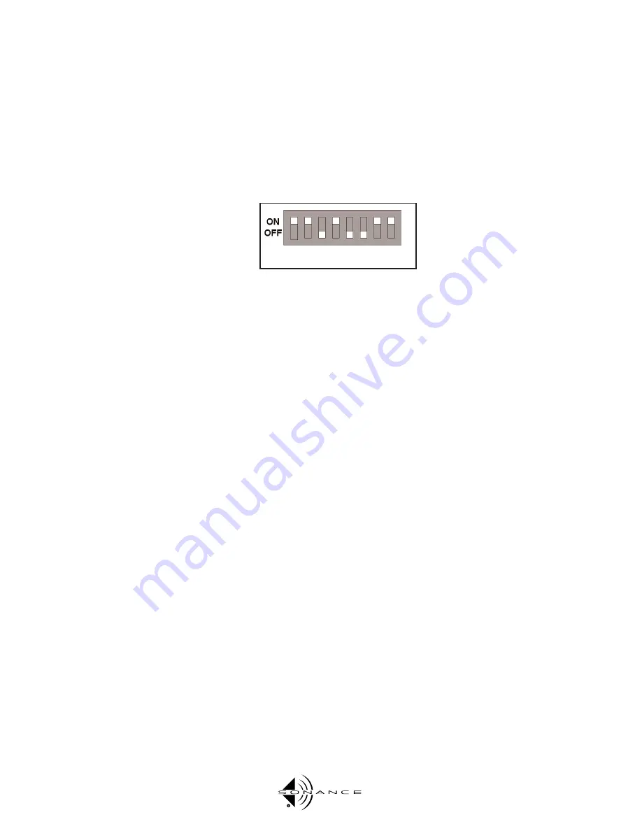
The example below depicts switches 1,2,4,7 and 8 in the “On”position
This example is Audio Keypad 1.
SETTING KEYPAD ADDRESSES AFTER THEY HAVE BEEN INSTALLED
Once the keypads are installed, it is still possible to verify the network address without remov-
ing them from the walls. Chances are you’ll need to remove them all and reset their switches,
but you may find that only one or two are wrong...
All that is required is proper wiring from the keypads to the Network Hub and power to the
hub. (Unplugging the Control 2’s network connector, if it’s up and running, will make check-
ing IDs easier.)
By pressing all six source buttons on an Audio Keypad simultaneously, the source buttons will
illuminate displaying that keypad’s DIP switch address. If the button is illuminated, then the
corresponding switch is on. Source button 1 equals switch one, source button 2 equals switch
two, etc.
Relay Controllers are more difficult. Use caution when setting them.
Keypad Configuration Tips
Do not apply power to the keypads until proper wiring has been verified. Reversed wiring will
damage the keypad.
All keypads must have a unique address for the system to function properly, even if the key-
pads are to be used in the same zone.
DIP switch settings can be verified after the keypad has been installed into the wall. Pressing
the top six buttons will cause the keypad to display a representation of its DIP switch setting
by illuminating its button LEDs. Button 1 illuminated indicates switch 1 is in the "On" posi-
tion, button 2 illuminated indicates switch 2 is "On," and so on. The "Off" button does not
illuminate.
When the switches are properly set, the button pattern on the keypad should match the illus-
trations on the right.
11010011