background image

AquaVent Quick Start Guide

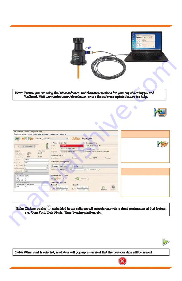
4. Connect the USB Connector 

Cable to the 10-Pin (Solinst 

Protocol) connection on the 

Wellhead, then plug the USB 

Connector Cable into your 

computer.

Programming AquaVent Loggers

Note: 

Ensure you are using the latest software, and firmware versions for your AquaVent logger and  


Wellhead. Visit www.solinst.com/downloads, or use the software update feature for help. 

1. Start the Levelogger Software, and select the appropriate Com Port for the connected device. 
2. In the Datalogger Settings tab, click the ‘Retrieve Settings” icon. This will display the 

current programmed settings for the connected AquaVent.   

3. You can now customize the AquaVent Project ID, Locations, sampling regime, and start and 

stop times.    

AquaVent Datalogger Settings Window

Note:

 Clicking on the 

 embedded in the software will provide you with a short explanation of that feature,  


e.g. Com Port, Slate Mode, Time Synchronization, etc.

Starting and Stopping AquaVent Loggers

1. If desired, enter a Future Start and/or Future Stop time. 
2. When the ‘Start’ icon is selected, all settings are applied to the AquaVent logger and it will start 

logging at the specified time. 

3. To start logging immediately, do not fill in the Future Start field, and click the ‘Start Now’ icon.

Tip

If a number of  

AquaVent loggers  

are to be programmed 

with identical inputs, clicking 

the “Save Default Settings” 

icon will create a template. 

Note:

 When start is selected, a window will pop-up as an alert that the previous data will be erased. 

4.  To stop the AquaVent immediately, click the “Stop Now’ icon. 

Tip

The ‘Future Start’ and 

‘Future Stop’ options are 

ideal for synchronizing the 

data collection of multiple  

loggers. 

USB Connector Cable

- 3 -

Содержание AquaVent 3500

Страница 1: ...High Quality Groundwater and Surface Water Monitoring Instrumentation Quick Start Guide 3500 AquaVent Please read this document carefully before using the AquaVent...

Страница 2: ...Wellhead Vented Cable AquaVent Logger 10 Pin SP Connection Alignment socket in the Vented Cable connectors Alignment pin in the Wellhead and logger connectors Coupling Connector Body Line up the alig...

Страница 3: ...gger Settings Window Note Clicking on the embedded in the software will provide you with a short explanation of that feature e g Com Port Slate Mode Time Synchronization etc Starting and Stopping Aqua...

Страница 4: ...view rate is set independently of the logging period of the AquaVent and does not interfere with internal logging taking place To take a reading at any specific time click and that reading will be add...

Страница 5: ...reference datum in the Manual Data Adjustment option in the Software Data Wizard AquaVent loggers detect both water W and barometric pressure B However a vent tube to surface allows barometric effect...

Страница 6: ...g 4 using an adaptor However other installations are acceptable if proper precautions and recommendations are followed Leave at least 2 50 mm of slack in the Vented Cable at surface to allow you to li...

Страница 7: ...ing blue red USB connection has been dropped Flashing yellow The Wellhead is communicating with the PC Software Maintenance As with any monitoring project you should select the proper equipment and de...

Страница 8: ...e bottom of the battery holder 2 Check the Vented Cable connections to the AquaVent logger and Wellhead Ensure they are lined up correctly and there is no dirt or debris in the connection 3 Make sure...

Отзывы: