background image

Installation and Operation Manual (Rev E) 

SGI Series Inverters       


DOCR-060371 


13 


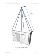
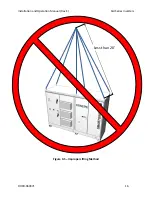
Figure 3.2 – Preferred Straight-Chain Lifting Method 

Содержание SGI 225

Страница 1: ...SGI 225 SGI 250 SGI 266 SGI 300 SGI 500 SGI 500PE INSTALLATION AND OPERATION MANUAL Revision E 2012 Solectria Renewables LLC ...

Страница 2: ...Rev E SGI Series Inverters IMPORTANT REGISTRATION AND WARRANTY INFORMATION For warranty to become active this inverter must be registered To activate warranty and register inverter please visit the link below www solren com registration ...

Страница 3: ...reduce the risk of electrical shock and to ensure the safe installation and operation of the inverter the following safety symbols are used to indicate dangerous conditions and important safety instructions WARNING This indicates a fact or feature very important for the safety of the user and or which can cause serious hardware damage if not applied appropriately Use extreme caution when performin...

Страница 4: ...th a key Keep the key in a safe location in case access to the cabinet is needed A replacement key can be purchased from Solectria Renewables SAVE THESE INSTRUCTIONS PRESCRIPTIONS DE SECURITE IMPORTANTES Tous les travaux d installation électrique doivent être exécutés en conformité aux normes électriques locales ainsi qu à la norme nationale américaine et canadienne Le SGI ne contient aucune pièce...

Страница 5: ... AC Connections to the Electrical Utility Grid 17 4 1 Grounding Electrode Conductor GEC 17 4 2 Equipment Grounding Conductor EGC 18 4 3 DC Subcombiner Wiring 19 4 4 DC Ground Fault Detection and Interruption 24 4 5 AC Wiring 25 4 6 AC Ground Fault Detection 28 4 7 Lightning and Surge Protection 28 4 8 Remote Shutdown Wiring 28 4 9 SolrenView Monitoring 30 4 10 SolrenView Air Monitoring 30 5 0 Comm...

Страница 6: ...9 0 Technical Data 45 9 1 Input DC PV Specifications 46 9 2 Output AC Specifications 47 9 3 Other Specifications 49 9 4 Internal Circuit Diagram 52 10 0 Appendices 53 10 1 Appendix A SGI 225 SGI 250 SGI 266 SGI 300 SGI 500PE and SGI 500 Data Sheet 53 10 2 Appendix B String Sizing Tool 53 10 3 Appendix C Contact Information 53 10 4 Appendix D Authorized Distributors 53 10 5 Appendix E UL1741 IEEE 1...

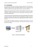
Страница 7: ...hase commercial industrial institutional or electrical utility facility s electrical system which is connected to the electrical grid If the PV system and inverter are providing the same amount of electrical power that the facility is using then no power is taken from or fed into the utility grid If the facility is using more power than the PV system is providing then the utility grid provides the...

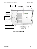
Страница 8: ...Front DC disconnect switch LEDs LCD display and keypad Nameplate specs and ETL UL1741 IEEE1547 CSA certification labels Warning label Lift eyes Cooling air intake Left side of enclosure contains integrated inverter filters and contactor Right side of enclosure contains isolation transformer and inductors ...

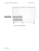
Страница 9: ...Installation and Operation Manual Rev E SGI Series Inverters DOCR 060371 3 Figure 1 3 The SGI Inverter Rear Exhaust air vents ...

Страница 10: ...nting Because the power electronics are within the rainproof main enclosure the inverter can be mounted outdoors The maximum life for the inverter can be achieved by mounting the unit in a clean dry and cool location For optimal electrical system efficiency use the shortest possible AC and DC cables and use the maximum allowable cable size Avoid installation in close proximity to people or animals...

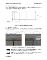
Страница 11: ...S A minimum distance of 18 inches must be clear behind the inverter for cooling air exhaust and service access A clearance distance of 36 inches behind the inverter is highly recommended to aid in cleaning the exhaust screens A minimum distance of 12 inches must be clear above the inverter for ventilation A minimum distance of 6 inches must be clear to the sides of the inverter If you are installi...

Страница 12: ...C breaker To check if the inverter is properly leveled the top of each pair of doors should be aligned with one another If the top edges are not aligned level the inverter by placing aluminum shims under the appropriate mounting foot prior to securing the inverter Acceptable Door Alignment Incorrect Door Alignment Figure 2 2 Leveling the Inverter for Proper Door Alignment NOTE Failure to properly ...

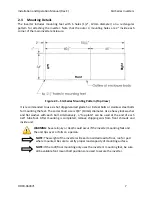
Страница 13: ...rect bolt size is 3 8 10mm diameter Use a heavy lock washer and flat washer with each bolt Alternatively a toe plate can be used at the end of each 4x4 tube foot After mounting is completed remove shipping aids from front shrouds and inside unit WARNING Severe injury or death could occur if the inverter mounting fails and the unit tips over or falls on a person NOTE The weight of the inverter will...

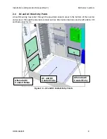
Страница 14: ...ing must enter through the provided conduit cutout in the bottom of the inverter enclosure or through the alternate conduit entries Alternative locations are the left side for DC and back panel for AC Figure 2 4 AC and DC Conduit Entry Points AC and DC Conduit Plate Alternate AC Conduit Entry Alternate DC Conduit Entries ...

Страница 15: ...Installation and Operation Manual Rev E SGI Series Inverters DOCR 060371 9 Fig 2 5 Alternate DC Conduit Entry Locations Figure 2 6 Alternate AC Conduit Entry Location ...

Страница 16: ...igorously before it is shipped Even though it is bolted onto a rugged oversized pallet for delivery the inverter can be damaged during shipping by poor handling trucking or transfer station activity Please inspect the inverter thoroughly after it is delivered If any damage is seen please immediately notify the shipping company to make a claim If there is any question about potential shipping damag...

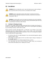
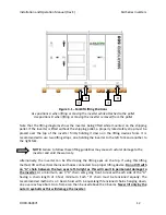
Страница 17: ...to the pallet and moved as close as possible to the final location prior to removing the pallet To remove the securing bolts use a 9 16 socket and or wrench Completely remove each nut and bolt from the pallet The center of gravity of the inverter is well to the right of center and is marked with a label on the left door of the transformer enclosure right half of the enclosure Use an 8 000lb capabl...

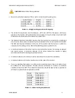
Страница 18: ... and another to the right fork NOTE Failure to follow these lifting guidelines may cause structural damage to the inverter and void the warranty Alternatively the inverter can be lifted using the lifting eyes on the top If using this lifting method lift with vertical chains and hooks connected to a proper lifting device Do not lift with an A chain between the two eyes left to right as this will re...

Страница 19: ...Installation and Operation Manual Rev E SGI Series Inverters DOCR 060371 13 Figure 3 2 Preferred Straight Chain Lifting Method ...

Страница 20: ...Installation and Operation Manual Rev E SGI Series Inverters DOCR 060371 14 Figure 3 3 Minimum Requirements for Eyebolt Lifting 4 Minimum ...

Страница 21: ...Installation and Operation Manual Rev E SGI Series Inverters DOCR 060371 15 Figure 3 4 Marginal Lifting Method 20 Minimum ...

Страница 22: ...Installation and Operation Manual Rev E SGI Series Inverters DOCR 060371 16 Figure 3 5 Improper Lifting Method Less than 20 ...

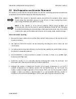
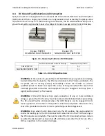
Страница 23: ...nductor GEC As with all PV systems a Grounding Electrode Conductor must be installed per NEC 690 This conductor should be sized according to NEC requirements Both a DC and AC GEC may be required at the inverter in some instances Two lug positions are provided on the ground bond plate for the AC and DC grounding electrode conductors Figure 4 1 AC and DC GEC Lug Positions Cu or Al Conductors Max 1 x...

Страница 24: ...quipped with a number of provisions for equipment grounding conductors In most instances these will be used for the equipment grounds originating at the combiner boxes used to feed the subcombiner positions within the inverter Figure 4 2 EGC Lug Positions Cu or Al Conductors Max 28 x 14AWG 1 0AWG 75C connections 50 in lbs 1 wire per lug position ...

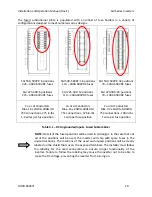
Страница 25: ...r must only be replaced with the same type and rating 600VDC fuses as originally installed The SGI series of inverters must be ordered with either an integral subcombiner populated with DC fuses or an integral subcombiner populated with DC breakers Many choices are available to meet any design constraint For the 225 400A fused or breaker subcombiner choose any combination of current ratings from 2...

Страница 26: ... position Cu or Al Conductors Max 16 x 2AWG 300kcmil 75C connections 375 in lbs 1 wire per fuse position Cu or Al Conductors Max 32 x 6AWG 1 0AWG 75C connections 100 in lbs 1 wire per fuse position Table 4 1 DC Ungrounded Inputs Fused Subcombiner NOTE Not all of the fused positions will be used in all designs In the case that not all of the positions will be used the inverter will ship with spare ...

Страница 27: ... 75C connections 550 in lbs 1 2 wires per lug Cu or Al Conductors Max 16 x 2AWG 300kcmil 75C connections 550 in lbs 2 wires per lug Cu or Al Conductors Max 32 x 6AWG 1 0AWG 75C connections 50 in lbs 1 wire per lug position Table 4 2 DC Grounded Inputs Fused Subcombiner The grounded DC connections are bonded to the ground system within the inverter through the ground fault detection and interrupt G...

Страница 28: ...nnections 275 in lbs 5 16 hex and 375 in lbs 3 8 hex 2 wires per breaker position Cu or Al Conductors Max 16 x 2AWG 300kcmil 75C connections 275 in lbs 1 wire per breaker position Table 4 3 DC Ungrounded Inputs Breaker Subcombiner NOTE Not all of the breaker positions will be used in all designs In the case that not all of the positions will be used the inverter will ship with breakers in the unus...

Страница 29: ...per lug or Max 16 x 2 0AWG 250kcmil 75C connections 550 in lbs 2 wires per lug Cu or Al Conductors Max 16 x 2AWG 300kcmil 75C connections 550 in lbs 2 wires per lug Table 4 4 DC Grounded Inputs Breaker Subcombiner The grounded DC connections are bonded to the ground system within the inverter through the ground fault detection and interrupt circuit GFDI The PV grounded connections should not be bo...

Страница 30: ...nnects the PV array combiners the PV panels the PV racking system Immediately contact the installer or another qualified person to locate and repair the source of the ground fault Be aware that normally grounded conductors and equipment may be energized and may pose a significant shock and or fire hazard WARNING If the GFDI breaker trips upon connection of one or more combined strings a ground fau...

Страница 31: ...00 Rated SGI 225 480VAC 400A 25 kAIC No SGI 250 480VAC 400A 35 kAIC No SGI 266 480VAC 400A 35 kAIC No SGI 300 480VAC 400A 35 kAIC Yes SGI 500 480VAC 800A 65 kAIC No SGI 500PE 480VAC 800A 65 kAIC No Table 4 6 Factory Included AC Breaker Minimum Specifications If the onsite electrical service connection is designed with an overcurrent protection device OCPD it must be dedicated to the PV system and ...

Страница 32: ...80VAC 2 3 0AWG 500kcmil 275 in lbs SGI 250 480VAC 2 3 0AWG 500kcmil 275 in lbs SGI 266 480VAC 2 3 0AWG 500kcmil 275 in lbs SGI 300 480VAC 2 4 0AWG 500kcmil 275 in lbs SGI 500 480VAC 3 250kcmil 400kcmil 375 in lbs SGI 500PE 480VAC 3 250kcmil 400kcmil 375 in lbs Table 4 8 Factory Included AC Breaker Phase Wire Size Limits The SGI series of inverters require a clockwise phase sequence for proper oper...

Страница 33: ...ormer s neutral bar has also been designed with a set of holes to allow for various field connections such as a box lug or a crimped lug SGI 500 PE Neutral Routing Path SGI 500 500PE Neutral Landing Location SGI 500 500PE Alternate Transformer Neutral Location SGI 225 300 Neutral Routing Path SGI 225 300 Neutral Landing Locations SGI 225 300 Alternate Transformer Neutral Location Cu or Al Conducto...

Страница 34: ...ection beyond the inverter s IEEE 1547 requirements The best protection against damage from lightning and other voltage surge sources is proper grounding of the system When required by local codes it is recommended to establish a grounding electrode system specifically for the PV array located as close as practical to the array It is also recommended to have the lightning protection system of the ...

Страница 35: ...ire the positive conductor to the left bottommost position on Terminal Block 18 Wire the return conductor to the left bottommost position on Terminal Block 19 Figure 4 5 Terminal Block Locations Figure 4 6 Remote Shutdown Wiring Locations on Terminal Blocks 18 and 19 Block 1 Block 2 a bottom a 19 1 2 3 4 5 6 7 8 9 10 11 12 13 14 15 16 17 18 b Remote shutdown in customer wire Remote shutdown return...

Страница 36: ...verter then to a router or switch for connection to the customer s broadband internet service To enable the SolrenView monitoring follow these steps using the display panel 1 Press to enter the display set mode 2 Press to MONITOR 3 Press to enter monitor set mode 4 Press to SRV Mode 5 Press to activate the change mode 6 Press to select Yes 7 Press to confirm 4 10 SolrenView Air Monitoring If you h...

Страница 37: ...aster blinking green LED Watch the LCD display for prompts and system status Listen for contactor closing inverter on line Listen for slight 60 Hz hum transformer on line Following the blinking green LED and high frequency switching sound you should see a solid green LED This confirms that the inverter is operating normally The LCD display will show the AC Power PAC Energy EAC current and voltage ...

Страница 38: ...ally without the need for user interaction The LCD display and Led indicators on the front door of the inverter provide valuable inverter operating information 6 1 LCD Display Figure 6 1 LCD Display 6 2 Button Description To move up a level from the current menu To scroll up or down within the individual menu items To enter into selected menu ...

Страница 39: ...Wh AC Power AC Power output W AC Voltage AC Voltage Three phase V AC Freq AC Frequency Hz AC Current average AC Current Three phase average A DC Voltage DC Voltage V Apparent Power Apparent AC Power output VA Reactive Power Reactive AC Power output VAr Reactive Avail Available Reactive AC Power output Var React Energy Cumulative reactive energy generated kVArh React Energy Cumulative reactive ener...

Страница 40: ...nsformer model 14 Limit Power Limit AC Power 15 UL Reconnect Wait time in minutes seconds 16 Password 4 digit pin code to set limits Note data is only available when inverter is operating Inverter Events Menu This displays inverter errors event history Timestamps are formatted as MM DD YY 1 Err Counts Displays cumulative counters for each supported event error with the highest error count shown fi...

Страница 41: ... then used as the fallback IP 2 Gateway IP IP address of LAN s default gateway 3 Netmask Subnet mask 4 Date Time Manual time set This may be overwritten by scheduled NIST updates 5 Reboot Reboots the monitor 6 Remote SRV This starts the transmit process necessary for SolrenView monitoring Note Enabling this option when SolrenView service has not been purchased will result in unnecessary wear on th...

Страница 42: ...r or fault YELLOW indicates that a ground fault in the PV array has been detected and it must be located and repaired before the inverter will function Check GFDI breaker if YELLOW LED remains solid Figure 6 2 LED Indicators GREEN A ground fault has been detected in the PV array DO NOT TOUCH any equipment including but not limited to the inverter the PV array disconnects the PV array combiners the...

Страница 43: ...than the low limit Measure the actual VAC compared to the LCD display VAC If VAC is less than acceptable limits inverter will restart when normal The AC grid frequency is exceeding the high limit If possible measure the frequency or contact local utility provider The AC grid voltage is less than the low limit If possible measure the frequency or contact local utility provider The AC contactor or s...

Страница 44: ... the voltage sensing circuit has occurred Turn off the inverter and contact Solectria Renewables The inverter may need to be serviced by an authorized service provider One of the AC phases is not present at the inverter Verify that there is AC voltage on all phases at the inverter and all fuses are intact An internal failure of one of the magnetic components Turn off the inverter and contact Solec...

Страница 45: ...I 7500 inverters the warranty period is 120 months from the date of purchase by the end user or 124 months after the delivery date from Solectria Renewables to the distributor or the dealer installer whichever is shorter If Solectria Renewables repairs or replaces a product its warranty continues for the remaining portion of the original Warranty Period or 90 days from the date of the repair repla...

Страница 46: ...For Alaska Hawaii and all other installation locations Solectria Renewables will cover the cost of return shipment of product one way from the customer The warranty does not include customs fees broker fees or other taxes that may be imposed by the government agency Contact Solectria Renewables customer service for details on the freight policy for return shipments outside of the contiguous United...

Страница 47: ...oduct if it has been misused neglected improperly installed physically damaged or altered either internally or externally or damaged from improper use or use in an unsuitable environment b The product if it has been subjected to fire water generalized corrosion biological infestations acts of God or input voltage that creates operating conditions beyond the maximum or minimum limits listed in the ...

Страница 48: ...ERS MANUFACTURERS VENDORS SUBCONTRACTORS DISTRIBUTORS DEALERS AND ANY OTHER AFFILIATES BE LIABLE FOR ANY SPECIAL DIRECT INDIRECT INCIDENTAL OR CONSEQUENTIAL DAMAGES LOSSES COSTS OR EXPENSES HOWEVER ARISING WHETHER IN CONTRACT OR TORT INCLUDING WITHOUT RESTRICTION ANY ECONOMIC LOSSES OF ANY KIND ANY LOSS OR DAMAGE TO PROPERTY INCLUDING LOSS OF USE AND INTANGIBLE HARM OF ANY KIND AND ANY PHYSICAL DA...

Страница 49: ... NO RESPONSIBILITY OR LIABILITY FOR LOSSES DAMAGES COSTS OR EXPENSES WHETHER SPECIAL DIRECT INDIRECT CONSEQUENTIAL OR INCIDENTAL WHICH MIGHT ARISE OUT OF THE USE OF SUCH INFORMATION THE USE OF ANY SUCH INFORMATION WILL BE ENTIRELY AT THE USERS RISK WARNING LIMITATIONS ON USE Please refer to your product user manual for limitations on uses of the product Specifically please note that Solectria Rene...

Страница 50: ...del names and serial number of your product Preparing the product for shipping 1 Package the unit safely preferably using the original box and packing materials Please ensure that your product is shipped fully insured in the original packaging or equivalent This warranty will not apply where the product is damaged due to improper packaging 2 Include the following a The RMA number supplied by Solec...

Страница 51: ...hest open circuit voltage occurs when the PV modules are at the coldest temperature and in bright sun Because the PV modules also have a reduction in voltage at high cell temperatures you must make sure the MPPT voltage of the strings will not drop below the minimum inverter DC input voltage in very hot temperature conditions Both the maximum open circuit voltage OCV when at cold extreme and minim...

Страница 52: ...s Operating voltage range low voltage option 285 600 VDC Input voltage MPPT range low voltage option 285 500 VDC Strike Voltage low voltage option 370 VDC Maximum input current low voltage option 808 898 956 1080 1812 1803 ADC Continuous input current low voltage option 808 898 956 1080 1812 1803 ADC All Units DC voltage measurement accuracy 2 Max continuous input power 230 5 256 272 5 308 516 5 k...

Страница 53: ...utility specific order codes Over voltage trip magnitude adjustability 100 120 Vnom Under voltage trip magnitude adjustability 50 100 Vnom Over under voltage trip time adjustability 0 1 30 sec Voltage measurement accuracy 2 Operating frequency adjustability 60 3 0 0 5 Hz Under frequency trip time adjustability 0 16 300 sec Frequency measurement accuracy 0 1 Hz Maximum Rated Output Current 208VAC e...

Страница 54: ...rmonic distortion THD full power 3 Power Factor Unity 0 99 Anti islanding protection per UL1741 IEEE1547 CSA22 2 107 1 Peak Efficiency 97 99 97 98 97 96 97 90 97 87 98 3 CEC Weighted Efficiency 97 5 97 5 97 5 97 5 97 0 97 5 97 5 for SGI 500PE 480 only Table 9 2 AC Output Specifications ...

Страница 55: ... 70A 400A fuses available 6 32 poles DC Breaker Subcombiner Range 110 400A breakers available 6 16 poles DC Disconnect Integral Break load rated Operational Ambient Temperature 40 to 50 C full power Storage Temperature 40 to 70 C Cooling Automatic Forced Convection Inverter Enclosure Rain Proof per UL1741 NEMA 3R Switching Electronics Enclosure IP 62 sealed design Sound Pressure Level A Weighting ...

Страница 56: ...Installation and Operation Manual Rev E SGI Series Inverters DOCR 060371 50 Figure 9 1 AC Output Power of SGI Series Inverters ...

Страница 57: ...Installation and Operation Manual Rev E SGI Series Inverters DOCR 060371 51 Figure 9 2 Efficiency of SGI Series Inverters at 360VDC Input and 25C Ambient Temperature ...

Страница 58: ... The basic power flow within the SGI series of inverters is shown in the simplified one line diagrams below Note that the GFDI circuit is not depicted Figure 9 3 Simplified Internal Circuit Diagram for SGI 500 480VAC Figure 9 4 Simplified Internal Circuit Diagram for SGI 225 480VAC through SGI 300 480VAC ...

Страница 59: ...tring Sizing Tool http www solren com stringSizing html 10 3 Appendix C Contact Information Solectria Renewables LLC 360 Merrimack Street Building 9 2nd floor Lawrence Massachusetts 01843 USA Tel 978 683 9700 Fax 978 683 9702 Sales general info inverters solren com Customer Support service solren com Website www solren com 10 4 Appendix D Authorized Distributors See website for complete and update...

Страница 60: ...Installation and Operation Manual Rev E SGI Series Inverters DOCR 060371 54 10 5 Appendix E UL1741 IEEE 1547 CSA22 2 107 1 Listing Letter ...

Страница 61: ...Installation and Operation Manual Rev E SGI Series Inverters DOCR 060371 55 ...

Отзывы: