


5
Commissioning
NOTE!
Frequently pressing the POWER button may cause a system error.
Wait at least 10 seconds after pressing the POWER button prior
to making another attempt.
Verify the model number of each battery module to ensure that
they are all
the
same model.
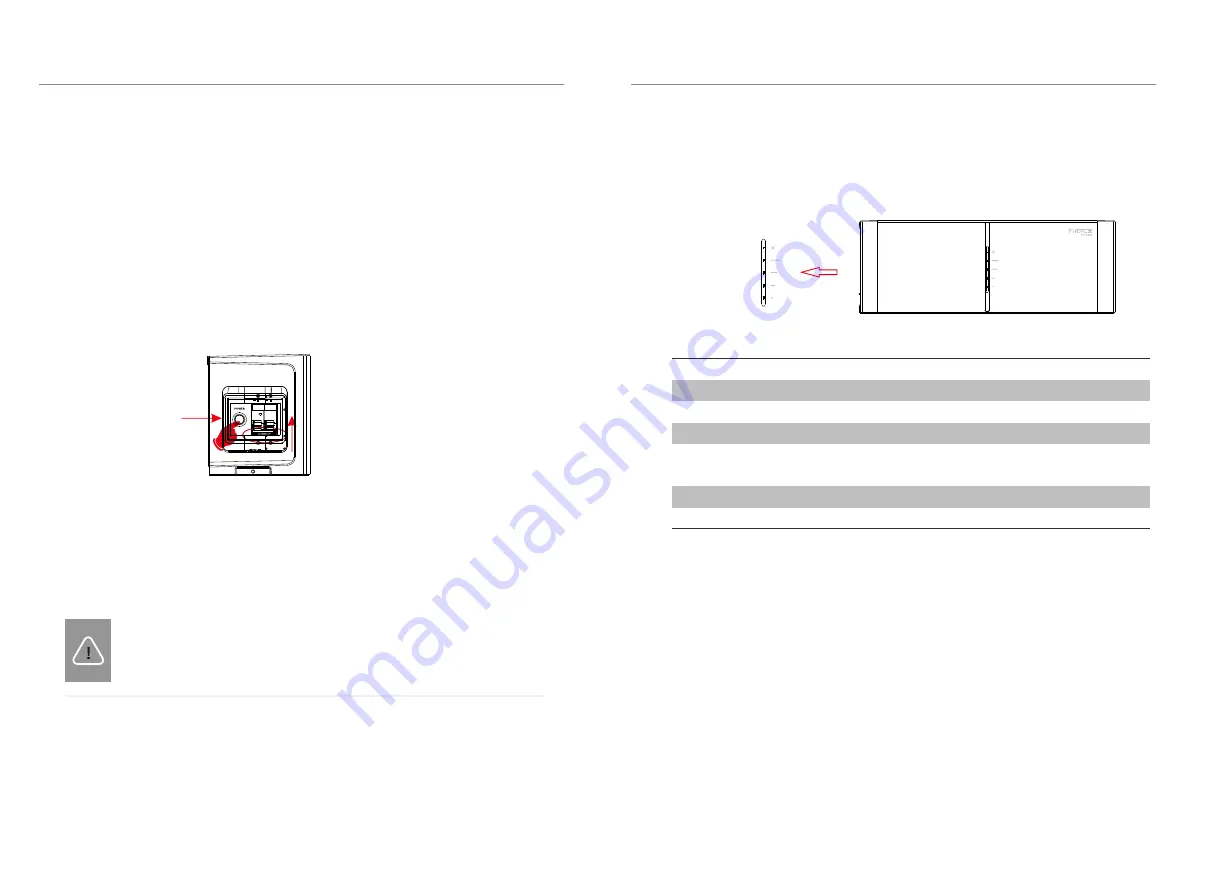
Once all battery module(s) are installed, follow these steps for beginning operation:
1) Open the cover board of the
BMS
2) Move the circuit breaker switch to the
ON position
4) Turn on the AC switch of inverter
5.1
COMMISSIONING
5. Commissioning
5. Commissioning
5.2
Status Indicators
No.
1
2
3
Mode
Power off
Inverter sends Idle command
BMS Protection
Status of BMS
The LED indicators on the front panel of the battery pack are showing the
operating status.
The capacity indicators show the SOC:
·
When the battery pack is neither charging nor discharging, the indicator
lights are o
ff
.
When the battery pack is charging, part of the Blue LED fashes with the
frequency of light on for 0.5s, light o
ff
for 0.5s, and part of the Blue LED keeps
light on. Take SOC 60% for instance, in charging state:
1). The first two Blue LED indicators keep on
2). The third Blue LED indicator flashes once every 1s
When the battery pack is discharging, the Blue LED fashes with the frequency
of light on for 1s, and light o
ff
for 4s. Take SOC 60% for instance, in discharging
state:
1). The first three blue LED indicators flash once every 5 seconds
The following table shows the status of BMS.
25
%
50
%
75
%
100
%
SOC
Status
The Green LED is light on for 0.3s, and light o
ff
for 0.3s
The Green LED keeps light on
Light off
The Green LED is light on for 1s, and light off
for 4s
The Orange LED is light on for 1s, and light off
for 4s
The Red LED keeps lighting on for 10min, then
flickers with light on for 1s, and light off
for 4s
Upgrade for BMS
Active
Fault
5
6
4
·
···
·
5.2.1
Battery Module (MC0600)
32
33
3) Long press the POWER button
for more than 1s to turn on the T-BAT system


