12
ASSEMBLY & INSTALLATION
GAS SUPPLY LINE
GAS SUPPLY LINE
GAS SUPPLY LINE
GAS SUPPLY LINE
The supply line should exit the wall that the fireplace will be installed on at the location specified on the
installation template we suggest the installation of a shut-off valve in the supply line between the wall
and the connection to the fireplace. Your professional gas installer or local gas company will determine
the specific requirements for the gas supply line as the requirements may vary in different locations. In
every case, the installation must conform with local codes or, in the absence of local codes, with the
National Fuel Gas Code, ANSI Z223.1.
INSTALLING THE FIREP
INSTALLING THE FIREP
INSTALLING THE FIREP
INSTALLING THE FIREPLACE
LACE
LACE
LACE
MOUNTING PLATE ON TH
MOUNTING PLATE ON TH
MOUNTING PLATE ON TH
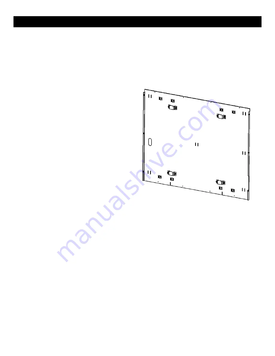
MOUNTING PLATE ON THE WALL
E WALL
E WALL
E WALL
1.
The fireplace mounting plate is attached to
the wall structure using four 1/4” X 1 1/2”
long lag bolts and large diameter washers
that are provided with the fireplace. It is
important to use the included hardware as
the full weight of the fireplace is supported
by the mounting plate.
2.
Drill a 5/32” diameter pilot hole at each of
the mounting hole locations that you
marked using the template. The pilot holes
should be the full depth of the lag bolts. Be
sure that there is solid wood at each
mounting location. If not, the wall should
be reconstructed to provide the needed
support.
3.
With a helper pick up and align the mounting plate over the gas supply line and line up with the
four mounting lag bolt pilot holes. These holes are in recessed bosses. Use either the 16” or 24”
on center holes depending on the construction of the wall.
4.
Using the lag bolts and washers provided with the fireplace, install the top lag bolts (with
washers) first, followed by the lower ones. Use a 7/16” socket wrench to tighten the lag bolts.
Note: It may be helpful to put a light coating of dish or hand soap on the lag bolts to reduce
resistance when tightening.
5.
At this point, check to be sure that there is an air gap between the entire flat back surface of the
mounting plate and the wall surface (see clearance chart on page 9 for the air gap required for
your model). This gap is critical to a safe installation and if the gap is obstructed in any way,
remove the obstruction before proceeding.
6.
Next check that the brackets on the mounting plate that actually hold the fireplace are level,
again using a spirit level. If the brackets are not perfectly level, you can adjust the right bracket
by loosening the bracket fasteners and moving the bracket until it is level with the left bracket.
Remember to tighten the bracket fasteners once you have achieved a level position. (refer to
images on following page)
Содержание FORTY6 VF
Страница 24: ...23 REMOTE HANDSET OPERATION ...
Страница 25: ...24 REMOTE HANDSET OPERATION ...
Страница 26: ...25 REMOTE HANDSET OPERATION ...
Страница 27: ...26 REMOTE HANDSET OPERATION ...
Страница 28: ...27 REMOTE HANDSET OPERATION ...
Страница 35: ...34 V1 5 20 15 ...


