1 About this manual
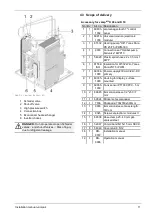
Accessory for vamp
air
K 12 and K 15
No Qty. Art. no. Designation
1
1
9345
Screw set electronic module II
2
1
9906
Immersion sleeve brass length:
140 cm
3
1
16401 Electronic volume flow sensor 5-
85 l/min
4
2
54787 Transition piece for volume flow
sensor KWP15
5
1
54920 Plastic spiral hose 22 x 3.5 mm f.
KWP, condensate drain hose
6
1
54947 Compriband-N15x15 mm SKVK
7
8
54949 Cover plug 8.5/12
8
1
54976 Pump ball valve with shut-off
valve DN32 Rp5/4" x G 2"
9
1
54977 Pump ball valve without shut-off
valve DN32 Rp5/4" x G 2"
10
2
54978 Insulation for pump ball valve DN
32
11
2
55035 Seal EPDM SH 70 2" KWP15
12
1
55051 Union nut G 2", set of 2 pcs
13
1
61526 Heating pump "HE" Stratos Para
30/1-8 T2-180
14
1
69034-
1000
Power supply 230V-AC/24V-DC
primary
15
1
69035-
1000
Housing for display, surface
mounted
16
2
69095-
1000
Tank sensor PT1000 PVC - 5 m
17
1
69803-
1002
ecomanager-touch 7" control
panel
18
1
69810-
1000
Universal module (electronic
module)
19
1
69336 Hose clamp 25 - 40 mm gal-
vanised steel
20
1
69645 Immersion sleeve 1/2"x50 / 7 mm
21
1
69824 Sticker set ecomanager
22
1
DR-
0072
Installation manual
23
1
DR-
0086
Operation manual
The parts in both accessory sets are packed in the
heat pump when delivered; for removal dismantle
cladding, see
Prepare heat pump
Not included in the scope of delivery: Heat pump pipe
; electric heating element
; lifting aid
; pri-
mary circuit connection set
4.4 Principle of operation
The function of a heat pump is similar to that of a ref-
rigerator from a technical standpoint, but reversed.
The refrigerator extracts heat from the food to be coo-
led and releases it to the room air.
The heat pump
vamp
air
withdraws heat from the out-
side air and delivers it to the heating system.
Four processes are decisive in the cooling circuit of
the heat pump:
Evaporation
The evaporator
(2)
takes the circulating refrigerant
energy from air and changes its state from liquid to
gaseous.
Compression
In an electrically driven scroll compressor
3
, the
gaseous refrigerant is heated by compression.
Liquefaction (condensation)
The absorbed thermal energy is delivered to the hea-
ting system. The gaseous refrigerant is cooled in the
condenser (plate heat exchanger) and liquefied again
4
.
Expansion
The pressure of the liquid refrigerant is reduced, resul-
ting in partial evaporation. The result is a mixture of
liquid and gaseous refrigerant (= wet steam). The ref-
rigerant cools down.
1 Energy from outside air
2 Evaporators
3 Scroll compressor
4 Condenser
5 Discharge of heating heat
6 Expansion valve
7 Economizer-heat exchanger (for Enhanced
Vaporized Injection)
8 Enhanced Vaporized Injection
12
Installation manual
vampair
Содержание Vampair
Страница 31: ...8 Electrical connection Installation manual vampair 31 8 5 Electrical connection plan ...
Страница 39: ...10 Foundation plan Installation manual vampair 39 Side view of foundation Section A A Abb 2 48 ...
Страница 44: ...Front view of foundation Section B B Abb 2 55 11 Flat roof set up 44 Installation manual vampair ...
Страница 51: ...12 Plant schematic Installation manual vampair 51 ...


