6 Install electric heating element
Wilo-Stratos PARA
(K 12, K 15)
–
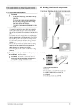
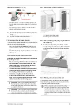
The flow sensor
1
must be installed upstream of
the circulation pump when viewed in the direction
of flow.
–
The calming section
2
before and after the flow
sensor must not be removed.
►
Connect the primary circuit circulation pump elec-
trically
►
Connect the flow sensor electrically
7.4 Connect the primary circuit
There are two fundamental options for connecting the
primary circuit to the heat pump:
–
Inlet from the heat pump
bottom
, (from the con-
crete foundation) with the
connection set bottom
–
Inlet from the heat pump
rear
, with the
connection
set rear
Both solutions are described in detail below.
Important installation information for connecting
the primary circuit
–
The connecting cable from the connection on
the heat pump to the building must be a fle-
xible connection. This is ensured by using
the SOLARFOCUS connection set.
–
The line routing must always provide a bend.
Avoid direct and straight line routing. Avoid
line routing under tension or pressure.
–
Avoid hose lengths smaller than 30 cm.
–
If these specifications are not adhered to,
there is a risk that vibrations and thus, noise
will be transmitted in the living space.
!
CAUTION
- Due to the oscillating bearing of
the heat pump unit, the hydraulic connection
to the heating system must not be carried out
as a rigid connection.
!
CAUTION
- The connection to the heating sys-
tem must not be carried out with stainless
steel corrugated pipes (material not suitable).
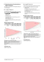
7.4.1 Connection on the condenser
Abb. 2-26
1 Primary circuit flow outlet
2 Primary circuit return inlet
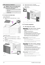
7.4.2 Cut insulating mat (only required for K
08 and K 10)
►
To introduce the primary circuit lines, cut the
soundproofing insulation (mat). After installation
of the pipes, pay attention to the best possible
sealing.
Abb. 2-27: Cut insulation mat
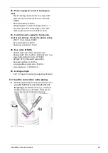
7.4.3 Primary circuit connection set
The SOLARFOCUS connection sets are supplied
from the factory suitable for direct connection to the
condenser (plate heat exchanger).
i
When using the optional electric heating
element, the flow line on the connection sets
must be shortened on site (the flow connec-
tion is located lower in the case of the electric
heating element than in the plate heat exchan-
ger).
Installation manual
vampair
23
Содержание Vampair
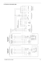
Страница 31: ...8 Electrical connection Installation manual vampair 31 8 5 Electrical connection plan ...
Страница 39: ...10 Foundation plan Installation manual vampair 39 Side view of foundation Section A A Abb 2 48 ...
Страница 44: ...Front view of foundation Section B B Abb 2 55 11 Flat roof set up 44 Installation manual vampair ...
Страница 51: ...12 Plant schematic Installation manual vampair 51 ...

