1 About this manual
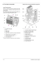
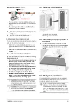
4.2 Functional components
vamp
air
K 08 and K 10
The fan
2
sucks the ambient air (outside air) through
the evaporator
3
and blows it out through the sound-
proofing slats
1
.
The condensate formed during defrosting of the eva-
porator is discharged through the outlet
8
.
Abb. 2-4
1 Soundproofing slats
2 Fan
3 Evaporators
4 Intake grille
5 Terminal area (electrical connection terminals)
6 Overtemperature reset (OTR)
[1]
7 Outside temperature sensor
8 Condensate drain
[1]Only when using electric heating element (optional accessory)
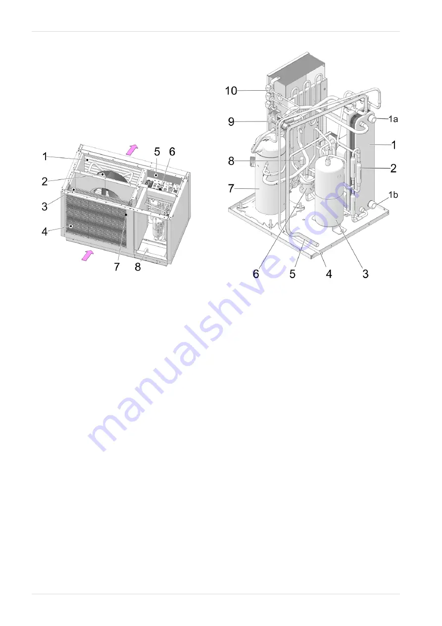
Components cooling circuit (without evaporator)
Abb. 2-5: View from behind - left
1 Condenser (plate heat exchanger)
1a Primary circuit flow outlet
1b Primary circuit return inlet
2 Non-return valve
3 Liquid collector
4 Fluid line to evaporator
5 Suction gas line from evaporator
6 Filter dryer
7 Scroll compressor
8 Expansion valve
9 Four-way switchover valve
10 Pressure sensors
10
Installation manual
vampair
Содержание Vampair
Страница 31: ...8 Electrical connection Installation manual vampair 31 8 5 Electrical connection plan ...
Страница 39: ...10 Foundation plan Installation manual vampair 39 Side view of foundation Section A A Abb 2 48 ...
Страница 44: ...Front view of foundation Section B B Abb 2 55 11 Flat roof set up 44 Installation manual vampair ...
Страница 51: ...12 Plant schematic Installation manual vampair 51 ...


