8 Electrical connection
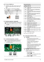
8.7.8 Device address of the electronic
module
The device address of the module can be adjusted
using the rotary switch S1.
Using the module as a ...
Device address
Electronic module D1
vamp
air
A
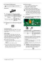
8.7.9 Elec. fuses in the electronic module
DANGER
- A fuse replacement may only be
carried out on a disconnected 230 V AC
power supply by qualified personnel.
Fuse Rating
Size
Assignment
F1
0.4 AT
5x20 mm
Primary-side
Supply transformer
F2
4 AT
5x20 mm
Relay outputs
F3
0.4 AT
5x20 mm
Secondary-side
Supply transformer
If fuse F1 or F3 is defective, a message will be shown
on the display of the
eco
manager-
touch
control:
Elec-
tronic module communication error
8.8 Outside temperature sensor - posi-
tion
Abb. 2-44
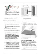
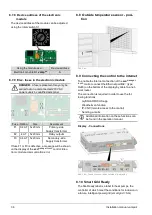
8.9 Connecting the control to the internet
To enable the Internet connection of the
eco
manager-
touch
control, connect the Ethernet port
X2
1
(type
RJ45) on the bottom of the display by cable to a net-
work router.
The connection is required in order to use the fol-
lowing functions:
–
mySOLARFOCUS app
–
Weatherman function
–
IP-VNC (remote access to the control)
–
Sending e-mails
i
Additional information on these functions can
be found in the operation manual.
Display - Connections
Abb. 2-45: Connections on the underside of the display
8.10 Smart Grid Ready
The SG-Ready label is a label for heat pumps, the
controller of which meet the conditions for inclusion in
a future, intelligent power grid
(smart grid
= SG).
36
Installation manual
vampair
Содержание Vampair
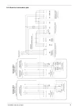
Страница 31: ...8 Electrical connection Installation manual vampair 31 8 5 Electrical connection plan ...
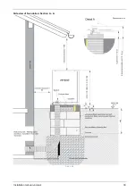
Страница 39: ...10 Foundation plan Installation manual vampair 39 Side view of foundation Section A A Abb 2 48 ...
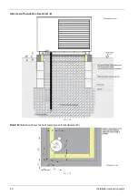
Страница 44: ...Front view of foundation Section B B Abb 2 55 11 Flat roof set up 44 Installation manual vampair ...
Страница 51: ...12 Plant schematic Installation manual vampair 51 ...


