background image

12. STANDARD EQUIPMENT AND OPTIONAL ACCESSORIES

48

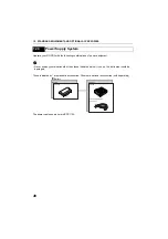
Operate your RC-PR3 with the following combinations of power equipment.

G

• Never use any combination other than those indicated below. If you do, the instrument could be 

damaged.

Those indicated by * are standard accessories. Others are optional accessories (sold separately)  

The power cable shown here is EDC113A

12.3

Power Supply System

Battery

BDC46B*

CDC68

EDC113A/113B/113C
(100 V AC)

Charger

Battery

Содержание RC-PR3

Страница 1: ...SURVEYING INSTRUMENTS On demand Remote Control System SYSTEM MANUAL RC PR3 Class 1 LED Product Class 1 Laser Product ...

Страница 2: ... This is the mark of the Japan Surveying Instruments Manufacturers Association ...

Страница 3: ...efully The specifications and general appearance of the instrument may be altered at any time and may differ from those appearing in brochures and this manual Some of the diagrams shown in this manual may be simplified for easier understanding The On demand Remote Control System adds remote control functions to the Series SRX NET05 NET1 and Series 230RM Please read this manual in conjunction with ...

Страница 4: ...WER etc Indicates RC controller LEDs Screens and illustrations Except where stated SRX means Series SRX NET means NET05 and NET1 total station means Series SRX NET05 NET1 Series 230RM and RC controller means the control unit for the On demand Remote Control System in this manual The content of this system manual is mainly concerned with explaining the operation of the RC controller Appended functi...

Страница 5: ... Tracking 24 6 3 Performing Turning from the SRX NET 26 6 4 Turning Error 28 7 APPENDED SETTINGS FOR THE SERIES 230RM 29 7 1 Beam Detector 29 7 2 Attaching Removing the Handle 29 7 3 Setup for Search Before Distance Measurement 30 7 4 Communication Setup 30 7 5 Performing Turning from the Series 230RM SFT Mode 31 7 6 Allocating Softkey Functions 32 7 7 Error Messages 33 7 8 Turning Error 33 8 BASI...

Страница 6: ...44 12 STANDARD EQUIPMENT AND OPTIONAL ACCESSORIES46 12 1 Standard Equipment 46 12 2 Optional Accessories 46 12 3 Power Supply System 48 13 SPECIFICATIONS 49 14 EXPLANATION 53 14 1 High Accuracy with the 360 Prism 53 15 REGULATIONS 54 ...

Страница 7: ...e symbol D This symbol indicates items which are prohibited Specific details are printed in or near the symbol I This symbol indicates items which must always be performed Specific details are printed in or near the symbol C Warning D Do not use the unit in areas exposed to high amounts of dust or ash in areas where there is inadequate ventilation or near combustible materials An explosion could o...

Страница 8: ... or throw batteries into fire An explosion could occur resulting in injury D Do not use the battery for any other purpose Fire or burns caused by ignition could result E To prevent shorting of the battery in storage apply insulating tape or equivalent to the terminals Otherwise shorting could occur resulting in fire or burns C Caution F Do not touch liquid leaking from batteries Harmful chemicals ...

Страница 9: ...ing the instrument with moisture or dust on the terminal or connectors may cause damage to the instrument Be sure to correctly attach the connector caps to protect the RC controller from moisture and dust particles when the connector is not in use Make sure that the inside of the carrying case and the instrument are dry before closing the case If moisture is trapped inside the case it may cause th...

Страница 10: ...e significant interference resulting in communication failure Perform communication at a distance of 3m or more from microwave ovens Refrain from using the RC controller in proximity to televisions and radios Televisions and radios use a different frequency band to Bluetooth communications However even if the RC controller is used within proximity to the above equipment with no adverse effects wit...

Страница 11: ...h the limit of usable range becoming lower as a result Similarly usable range may also shorten when performing communication in wooded areas Moreover as wireless devices lose signal strength when close to the ground perform communication at as high a position as possible G Sokkia cannot guarantee that all Bluetooth devices are compatible with the On demand Remote Control System ...

Страница 12: ...ury is caused by exposure to the laser beam seek immediate medical attention from a licensed ophthalmologist CCaution Perform checks at start of work and periodic checks and adjustments with the laser beam emitted under normal conditions When the instrument is not being used turn OFF the power When disposing of the instrument destroy the battery connector so that the laser beam cannot be emitted O...

Страница 13: ...red with that for the previous measurement to estimate the direction in which the RC controller moved following the previous measurement By then taking into account the aspect of the telescope the RC controller can instruct the total station regarding the quickest rotation direction to the prism The onboard electronic compass was calibrated before being shipped from the factory A function within t...

Страница 14: ...n the direction of the total station and instruct the instrument to start Turning A laser beam is emitted from the projection port At the same time the Bluetooth unit COM 1 relays the instruction to begin Turning 2 The total station begins to rotate horizontally searching for the emitted laser beam If it is not detected by the end of the second rotation an error occurs 3 Once the position of the h...

Страница 15: ...eld of view 5 The SRX NET tracks a sighted prism as it is moved to the next measurement point when Auto Tracking is set G The time limit for Turning is 60 seconds from the start of Turning operation If the operation exceeds this time limit an error occurs When Auto Tracking has been selected the SRX NET will start tracking a moving prism once Turning to that prism has been completed ...

Страница 16: ... the RC controller In this case the accuracy of measurement results may be adversely affected Fix the pole vertically over the measurement point For communication settings for data collectors etc see the operator s manual for your respective device XPROCEDURE 1 Connect the instruments C 5 SYSTEM CONFIGURATION 2 Switch ON the power to the total station Open the beam detector cover 3 Set measurement...

Страница 17: ...ance measurement Turning operation is carried out Measurement starts when this Turning operation is complete When returned laser signal is weak object with low reflection factor Even if the laser beam received by the total station has been reflected off an unrelated object or sunlight has entered the beam detector the total station still attempts to complete the stages of Turning operation as far ...

Страница 18: ...ible to specify the rotation direction for Turning operation before performing distance measurement C For operation procedure see the operator s manual for your data collector Height difference and slope distance The maximum measuring range depends on the height difference between the total station and the RC controller The shaded area in the graph below represents the measurement range when set t...

Страница 19: ... controller when using a wireless modem C 9 2 Setting Communication Mode 9 3 Communication Setup for the RC Controller Make sure the power of all instruments is off before connecting If the total station and RC controller are not connected correctly normal operation cannot be carried out Handle cables with care Grip the connected end of the cable when disconnecting Do not pull the cable out with u...

Страница 20: ...ndle contact your Sokkia agent Series 230RM instrument compatible with On demand Remote Control System G For details regarding data collectors and wireless modems compatible with the On demand Remote Control System contact your Sokkia agent Make sure the power of the date collector is off before connecting to the serial cable Series 230RM does not support Auto Pointing with a 360 Prism ATP1 5 2 Sy...

Страница 21: ... Configuration of the RC Controller RC Trigger grip for RC PR3 One touch Adapter Adapter Stainless steel Pin pole Pin pole Pin pole Pin pole prism foot AP66 SB184 Adapter Adapter SB184 Adapter SB184 360 Prism ATP1 360 Prism ATP1 Pin pole Prism OR1PA attachment SB182A SB183 SB183 RC PR3 RC PRH3 Controller ...

Страница 22: ...on of the SB179 and AP65B 65C is possible if Precise Tip of the AP65 is transferred to the AP65B 65C The One touch attachment SB179 SB179A can also be used to connect the 360 Prism ATP1 directly to the pole i e when the RC PR3 is not used Protector RP2 360 Prism RC controller attachment One touch Pole RC PR3 ATP1 The pole reading shows AP65B 65C AP65 65A SB179 SB179A SB179A the height from the bot...

Страница 23: ...e of the One touch attachment When attached without being aligned correctly the RC controller may not despite appearances be securely connected Attaching Releasing the One touch attachment Type 1 Type2 Slide the lock release button to the right then press to release the One touch attachment Locating plate RC controller base ...

Страница 24: ...Adjust until the locating plate is on the left with the graduations facing forward Connecting the 360 Prism to the RC controller Align the red dot on the RC controller with the 360 Prism as shown in the above diagram Locknut 2 Rotate the One touch attachment clockwise until the locknut meets the top of the pole Locating plate 4 Rotate the locknut towards the pole until secured in place Red dot ...

Страница 25: ...ion port of the RC controller C 14 1 High Accuracy with the 360 Prism RC Controller RC PR3 The RC controller comprises a control unit and wireless modem 5 4 Parts of the RC Controller Bluetooth antenna Control panel Communications Laser projection Battery cover Control panel side Laser projection port side port Control unit Wireless modem SEARCH LED connector ...

Страница 26: ...good communication conditions communication with the total station When the antennas of the SRX NET and RC controller cannot be positioned so as to be visible to one another point in a vertically downward position Communication with data collectors is performed using a second internal antenna The usable range of this modem is a line of sight distance up to approx 2m FAR SEARCH POWER FAR button SEA...

Страница 27: ...grip to the RC PR3 and then attach the RC PR3 to the instrument height adapter AP41 etc Holding the trigger grip keep the instrument level Check the position of the bubble of the circular level If the bubble is not off center no adjustment is necessary If the bubble is off center perform the following adjustment First confirm the off center direction Use the adjusting pin to loosen the circular le...

Страница 28: ...ooth communication causes SRX NET battery power to be depleted at a rate higher than that for normal operation When communicating between the SRX NET and RC controller using Bluetooth wireless technology COM 1 of the RC controller will be set as the Master device and the SRX NET will be set as the Slave device 1 Select Comms in SETTINGS mode Set Comms mode in the Comms setup tab to Bluetooth Check...

Страница 29: ...vice Set the data collector as the Master device C 8 3 Communication Status Bluetooth connections 3 The display returns to Meas mode and SRX NET enters Waiting mode Check that the RC controller Bluetooth mode is set to Master and power ON to initiate a connection C 9 3 Communication Setup for the RC Controller 4 When a connection has been successfully established is displayed in the status bar COM...

Страница 30: ...ce the SRX NET confirms that the prism is sighted at the approximate center of the field of view Auto Pointing is complete Although this setting provides greater accuracy when supporting the pole by hand hand movements will result in Auto Pointing taking too long to complete and a Time out error will occur When Rapid is set however Auto Pointing can be performed even with slight instability of pri...

Страница 31: ...rotation of the telescope The Shift point signifies the dial turning speed at which telescope rotation switches from the Lo speed setting to the Hi speed setting This Shift point along with the Lo and Hi speed settings can be configured according to user preference Settings and Options factory settings 1 Lo 1 to 4 3 steps 4 is fastest 2 Hi 1 to 4 3 steps 4 is fastest 3 Shift point 1 to 4 2 steps P...

Страница 32: ...eys change according to the settings made in A T Setting and Srch method in Motor configuration When Search is set 6 3 Performing Turning from the SRX NET Motor setting Softkey When Search set in A T Setting When None set in A T Setting Srch method is R C Srch method is G S Global Search SRCH Performs Auto Pointing DIST Performs Turning operation then angle distance measurement Performs Auto Point...

Страница 33: ...to Tracking Performs angle and distance measurement RC Rotates directly in the direction of the RC controller then performs Auto Pointing Rotates in the direction specified by the RC controller then performs Auto Pointing RC Rotates in a counterclockwise direction from the point of view of the RC controller then performs Auto Pointing Auto Tracking Rotates in a counterclockwise direction from the ...

Страница 34: ... this prediction If the SRX NET re acquires the target in this predicted direction Auto Tracking continues without change If the target is not re acquired however Auto Tracking will stop and the SRX NET will enter prism wait status for a period of 60 seconds If the target enters the field of view or a Turning command is received from the RC controller during prism wait the SRX NET will search for ...

Страница 35: ...over when using the On demand Remote Control System When measurement is complete make sure that the beam detector cover is closed before placing the instrument in its case The handle is attached removed using the screw located at the opposite end of the handle to the beam detector Supporting the handle with one hand use a coin to loosen the screw until the handle can be removed To attach align the...

Страница 36: ...t prism will be performed prior to distance measurement Search Auto Pointing only RC Turning Off No search G To perform measurement using the On demand Remote Control System the above setting must be set to RC To perform measurement without using the RC controller the above setting can be set to either Search or Off If it is set to RC by mistake an error will occur as the Series 230RM tries to fin...

Страница 37: ...wards the RC controller Turn right Series 230RM begins Turning in a clockwise right direction from the point of view of the operation panel Turn left Series 230RM begins Turning in a counterclockwise left direction from the point of view of the operation panel 3 To cancel Turning press STOP during operation 7 5 Performing Turning from the Series 230RM SFT Mode Aiming 7 H angle set 8 Data view 9 Me...

Страница 38: ...ess RC and the Series 230RM begins Turning directly towards the RC controller Press RC and the Series 230RM begins Turning in a counterclockwise left direction from the point of view of the operation panel Press RC and the Series 230RM begins Turning in a clockwise right direction from the point of view of the operation panel 7 6 Allocating Softkey Functions RC Meas Sdist PC 30 ppm 0 DIST P1 RC ZA...

Страница 39: ...tinue Turning operation For other softkeys see 7 6 Allocating Softkey Functions Remotocatcher Communication err Communication between the Series 230RM and RC controller has failed Check the status communications setup power supply cable connections etc of the RC controller wireless modem and cables Motor error E592 Motor error E593 A hardware error has occurred with the RC controller Switch the po...

Страница 40: ... on a warm boot occurs When installing removing the battery make sure that moisture or dust particles do not come in contact with the inside of the instrument XPROCEDURE Mounting the battery 1 Slide down the catches on the battery cover to open 2 Insert the battery in the direction of the arrow printed on the side 3 Close the battery cover A click is heard when the cover is secure XPROCEDURE Remov...

Страница 41: ... is over 100m normal atmospheric conditions 150m good atmospheric conditions Atmospheric conditions Normal slight haze visibility about 20 km sunny periods weak scintillation Good no haze visibility about 40 km overcast no scintillation G Set to Standard Mode FAR is Off when the total station and RC controller are close Using Far Mode FAR is Lit when the total station and RC controller are close c...

Страница 42: ... button during operation to stop Turning If the total station fails to detect the prism a long audio tone sounds and SEARCH Flashes quickly for approx 2 seconds to indicate that an error has occurred When the laser beam from the RC controller is reflected off a unrelated object the total station completes Turning operation pointing at this object instead of the RC controller When this happens pres...

Страница 43: ...lave To initiate connections from the SRX NET side set the SRX NET as the Master device To initiate connections from the paired device side set the SRX NET as the Slave device The factory setting for the SRX NET is Slave Bluetooth connections are as follows COM1 Total station Slave RC controller Master COM2 Data collector Master RC controller Slave 8 3 Communication Status Port Control panel statu...

Страница 44: ...ch 1 OFF when your RC controller was shipped from the factory Dip switch 3 sets the mode for communication between the RC controller and the total station Dip switch 4 sets the mode for communication between the RC controller and the data collector Dip switch 3 Dip switch 4 ON Serial communication mode Dip switch 3 Dip switch 4 OFF Bluetooth wireless communication mode Set Dip switch 3 to ON when ...

Страница 45: ...nction within the compass will automatically perform any necessary calibration in response to changes in the magnetic field Although this function by itself is sufficient in normal situations when the RC controller becomes highly magnetized manual calibration is necessary G When the power is ON automatic calibration is performed to adjust for changes in temperature and magnetic field When transpor...

Страница 46: ...hones tape measures etc or magnetic objects such as magnetic necklaces while performing manual calibration XPROCEDURE Checking whether manual calibration is necessary 1 Press the POWER button to switch ON the RC controller POWER is Lit If FAR and SEARCH flash and a rapid error tone sounds repeatedly relocate to a position several meters away from metallic objects desks steel frames etc or devices ...

Страница 47: ...dio tone sounds and the RC controller is switched ON in calibration mode FAR and SEARCH are Lit 2 Hold the RC controller vertical and press the SEARCH button FAR flashes red and calibration starts 3 Without moving the position of the RC controller rotate it 1 5 to 2 times in a horizontal direction G Rotate 1 5 to 2 times in approximately 10 seconds 1m or above ...

Страница 48: ...and press the SEARCH button FAR Flashes 6 Without moving the position of the RC controller rotate it 1 5 to 2 times in a horizontal direction 7 After rotating continue to hold the RC controller horizontal and press the SEARCH button 8 FAR turns Off 9 Push and hold the POWER button on the RC controller to switch OFF POWER turns Off and calibration is complete 1m or above ...

Страница 49: ... station is low or the total station has switched OFF Check the power to the total station C Operator s Manual Series SRX NET05 NET1 Series 230RM Operator s Manual FAR all LEDs Flashing quickly Hardware error Switch the power to the RC controller OFF and ON again If the error reoccurs after restart contact your Sokkia agent A long audio tone sounds and SEARCH Flashes quickly for approx 2 seconds T...

Страница 50: ...g battery power Turning operation failure The beam detector cover is closed Close the beam detector cover C 7 1 Beam Detector Both the laser projection port and the prism are not pointing in the direction of the total station Point the laser projection port and the prism towards the total station The total station cannot receive the beam emitted from the RC controller as the amount of light is too...

Страница 51: ... of the RC controller Continue Turning operation C 4 2 Measurement Flow C 6 3 Performing Turning from the SRX NET 7 5 Performing Turning from the Series 230RM SFT Mode The signal for the data collector wireless modem equipped with Bluetooth wireless technol ogy is weak The wireless modem signal is poor because the modem is placed in a low position close to ground level Place the modem in as high a...

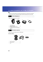
Страница 52: ...dicated protective case before inserting into the carrying case Please verify that all equipment is included For use with other prism types contact your Sokkia agent 360 Prism ATP1 12 1 Standard Equipment 12 2 Optional Accessories 1 RC PR3 main unit 1 2 Battery BDC46B 2 3 Carrying case SC220 220A 1 4 On demand Remote Control System Manual 1 1 360 Prism ATP1 1 2 Protective cover 1 3 Cap 1 ...

Страница 53: ... cover when the prism is not being used to protect the prism surface from dirt and damage The inner light grey section can be used as a cleaning cloth to wipe the surface of the prism Trigger Grip RC PRH3 Inner light grey cleaning cloth section 1 Trigger grip 1 2 Strap 1 3 Adjusting pin 1 ...

Страница 54: ... G Never use any combination other than those indicated below If you do the instrument could be damaged Those indicated by are standard accessories Others are optional accessories sold separately The power cable shown here is EDC113A 12 3 Power Supply System Battery BDC46B CDC68 EDC113A 113B 113C 100 V AC Charger Battery ...

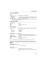
Страница 55: ...se 1 8m horizontal distance height of instrument point and measurement point is almost the same instrument height is 1 5m and prism height is 0 05m 3 About 20m height difference between instrument and RC controller laser projection port 4 About 40m height difference between instrument and RC controller laser projection port 5 Time taken between the start of the search and the obtaining of distance...

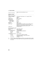
Страница 56: ...acles few vehicles or sources of radio emissions interference in the vicinity of the instrument no rain Authentication Yes No selectable Serial communication port 6 Data input output Computer data collector Interface RS232C compatible Communication settings 8 factory settings Baud rate 1200 2400 4800 9600 19200 38400 Data bits 7 8 bits Stop bit 1 2 bits Parity Not set Odd Even Compatible wireless ...

Страница 57: ...elevation and inclination both less than 10 EDM 1 3 to 1000m 10 Auto Tracking 2 to 500m 10 Auto Pointing 2 to 600m 10 Prism constant 7mm 3D positioning accuracy standard deviation 3mm Angles of elevation and inclination both less than 20 Prism height 37mm from mounting face flange face when attached to RC PR3 Operating temperature 20 to 50 C Storage temperature range 30 to 70 C Size 70 W X 104 H m...

Страница 58: ...peat Turning with the instrument turned 90 and distance measurement performed in Rapid measurement single every 1 minute General Size 202 W X 165 D X 383 H mm with handle Weight with handle and battery 3230RM 4230RM About 7 6kg ...

Страница 59: ... Prism toward the total station The 360 Prism should be set up so that a pair of diametrically opposed hexagonal points on its rubber flanges are aligned with the sighting direction of the total station see the diagram below 14 1 High Accuracy with the 360 Prism Hexagonal points ...

Страница 60: ...nna or transmitter This equipment complies with FCC radiation exposure limits set forth for uncontrolled equipment and meets the FCC radio frequency RF Exposure Guidelines in Supplement C to OET65 This equipment should be installed and operated with at least 20cm and more between the radiator and person s body excluding extremeties hands wrists feet and ankles For users in Canada This Class A digi...

Страница 61: ...55 15 REGULATIONS For users in the European Economic Area EEA ...

Страница 62: ...15 REGULATIONS 56 RC PR3 ...

Страница 63: ... equipo opera a titulo secundario consecuentemente debe aceptar interferencias perjudiciales incluyendo equipos de la misma clase y puede no causar interferencias a sistemas operando a titulo primario COFETEL RCPSOSM07 290 COFETEL RCPSOZE06 471 ...

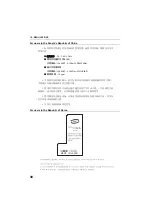
Страница 64: ...ㄝ Փ ᮍ ع Փ 乥 㧦2 4 2 4835 GHz ع 㟗 戟 䘖 EIRP 兎 䥙 10dBi 㢅 ื100 mW 㒥ื20 dBm ع 㦏 䘖廀 ㄵ 兎 䥙 10dBi 㢅 ื20 dBm MHz EIRP ع 戌欠 棟 20 ppm ϡᕫ᪙㞾 ᬍথᇘ乥 ǃࡴ থᇘࡳ ࣙᣀ乱 ࡴ㺙ᇘ乥ࡳ ᬒ ˈ ϡᕫ᪙㞾 㒓 ᬍ ᅗথᇘ 㒓 Փ ᯊϡᕫᇍ ড় ⱘ᮴㒓 䗮ֵϮࡵѻ ᆇᑆᡄ ϔᮺথ ᑆᡄ 䈵ᯊˈᑨゟे ذ ℶՓ ˈᑊ䞛প ᮑ 䰸ᑆᡄৢᮍৃ㒻㓁Փ Փ ᖂࡳ ᮴㒓 䆒 ˈᖙ乏ᖡফ ᮴㒓 Ϯࡵⱘᑆᡄ ᎹϮǃ ᄺঞ ए ᑨ 䆒 ⱘ䕤ᇘᑆᡄ ϡᕫ 亲ᴎ ᴎഎ䰘䖥Փ DŽ A12 RC1 A A12 SM BT1 A12 Z1 MADE IN JAPAN ...

Страница 65: ...59 15 REGULATIONS For users in Singapore For users in Taiwan For users in the United Arab Emirates Approved by TRA Complies with IDA Standards DB101547 ...

Страница 66: ...MEMO 60 ...

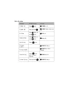
Страница 67: ...en turns Off Far Mode When FAR is Off press once FAR is Lit Standard Mode When FAR is Lit press once FAR is Off Start Turning Press once Turning in operation SEARCH Flashes Turning complete SEARCH is Lit for 2 seconds Cancel Turning Press once while Turning in operation SEARCH is Off Continue Turning Press and hold SEARCH Flashes ...

Страница 68: ... 2006 SOKKIA CO LTD JAPAN ...

Отзывы: