Sokkia CX-52 Скачать руководство пользователя страница 202

27. RECORDING DATA - TOPO MENU -

194

2.

Select “Occupy”.

3.

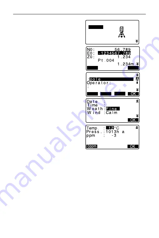
Set the following data items.
(1) Instrument station coordinates
(2) Point name
(3) Instrument height
(4) Code
(5) Operator
(6) Date (Display only)
(7) Time (Display only)
(8) Weather
(9) Wind
(10)Temperature
(11)Air pressure
(12)Atmospheric correction factor

• Select [LOAD] to recall and use 

the registered coordinates.

"12.1 Entering Instrument 

Station Data and Azimuth 
Angle PROCEDUR
E Reading 
in Registered Coordinate 
Data
".

• When inputting code, [ADD]

[LIST] and [SRCH] are 
displayed.
Press [ADD] to save input codes 
in memory.

Press [LIST] to display saved 
codes in reverse chronological 
order. 

Press [SRCH] to search for a 
saved code.

 For reviewing and saving 

codes in Data mode, see 
"29.3 Registering/Deleting 
Codes"
 and "29.4 Reviewing 
Codes"

TOPO   JOB1

Occupy 

Angle data

Dist data

Coord data

BS data

OK

LOAD

HI

PT

ADD

LIST

SRCH

CD

J a n / 0 1 / 2 0 1 2

1 7 : 0 2 : 3 3

P

Содержание CX-52

Страница 1: ...SURVEYING INSTRUMENTS OPERATOR S MANUAL CX 52 CX 55 Compact X ellence Station CLASS 3R Laser Product 1010291 01 A ...

Страница 2: ... This is the mark of the Japan Surveying Instruments Manufacturers Association Li ion S Li ion ...

Страница 3: ...ions from a host computer can also be performed For details refer to Communication manual and ask your local dealer The specifications and general appearance of the instrument are subject to change without prior notice and without obligation by TOPCON CORPORATION and may differ from those appearing in this manual The content of this manual is subject to change without notice Some of the diagrams s...

Страница 4: ...ures is based on the factory setting It is possible to change the allocation of softkeys in OBS mode What are softkeys 4 1 Parts of the Instrument Softkeys allocation 31 3 Allocating Key Functions Learn basic key operations in 5 BASIC OPERATION before you read each measurement procedure For selecting options and inputting figures see 5 1 Basic Key Operation Measurement procedures are based on cont...

Страница 5: ...ngle to a Required Value Horizontal Angle Hold 34 10 3 Angle Measurement and Outputting the Data 36 11 DISTANCE MEASUREMENT 37 11 1 Returned Signal Checking 38 11 2 Distance and Angle Measurement 39 11 3 Recalling the Measured Data 40 11 4 Distance Measurement and Outputting the Data 41 11 5 Coordinate Measurement and Outputting the Data 42 11 6 REM Measurement 44 12 SETTING INSTRUMENT STATION 47 ...

Страница 6: ...ging the Starting Point 129 21 SURFACE AREA CALCULATION 131 22 INTERSECTIONS 135 23 TRAVERSE ADJUSTMENT 139 24 ROUTE SURVEYING 148 24 1 Instrument Station Settings 148 24 2 Straight Line Calculation 149 24 3 Circular Curve Calculation 151 24 4 Spiral Curve 154 24 5 Parabola 160 24 6 3 Point Calculation 164 24 7 Intersection Angle Azimuth Angle Calculation 167 24 8 Route Calculation 169 25 CROSS SE...

Страница 7: ...gs 231 31 3 Allocating Key Functions 235 31 4 Changing Password 239 31 5 Restoring Default Settings 240 32 WARNING AND ERROR MESSAGES 241 33 CHECKS AND ADJUSTMENTS 246 33 1 Circular Level 246 33 2 Tilt Sensor 247 33 3 Collimation 250 33 4 Reticle 251 33 5 Optical Plummet 254 33 6 Additive Distance Constant 256 34 STANDARD EQUIPMENT AND OPTIONAL ACCESSORIES 258 34 1 Standard equipment 258 34 2 Opti...

Страница 8: ......

Страница 9: ...s main text Definition of Indication WARNING Ignoring this indication and making an operation error could possibly result in death or serious injury to the operator CAUTION Ignoring this indication and making an operation error could possibly result in minor injury or property damage This symbol indicates items for which caution hazard warnings inclusive is urged Specific details are printed in or...

Страница 10: ...observation 34 2 Optional accessories When securing the instrument in the carrying case make sure that all catches including the side catches are closed Failure to do so could result in the instrument falling out while being carried causing injury Do not use the carrying case as a footstool The case is slippery and unstable so a person could slip and fall off it Do not place the instrument in a ca...

Страница 11: ...ed battery charger to recharge batteries Other chargers may be of different voltage rating or polarity causing sparking which could lead to fire or burns Do not use the battery or charger for any other equipment or purpose Fire or burns caused by ignition could result Do not heat or throw batteries into fire An explosion could occur resulting in injury To prevent shorting of the battery in storage...

Страница 12: ...instrument is mounted Failure to tighten the screws could result in the tripod collapsing causing injury Do not carry the tripod with the tripod shoes pointed at other persons A person could be injured if struck by the tripod shoes Keep hands and feet away from the tripod shoes when fixing the tripod in the ground A hand or foot stab wound could result Tighten the leg fixing screws securely before...

Страница 13: ...istance when the battery cover is closed and connector caps are attached correctly Be sure to close the battery cover and correctly attach the connector caps to protect the CX from moisture and dust particles Make sure that moisture or dust particles do not come in contact with the inside of the battery cover terminal or connectors Contact with these parts may cause damage to the instrument Make s...

Страница 14: ... not depress open the battery cover to resume normal functionality To prevent the keys from becoming stiff remove the connector caps before moving the CX to a cold place Never place the CX directly on the ground Sand or dust may cause damage to the screw holes or the centering screw on the base plate Do not aim the telescope directly at the sun Also attach the lens cap to the telescope when not in...

Страница 15: ...n the rotatable portion screws or optical parts e g lens contact your local dealer When the instrument is not used for a long time check it at least once every 3 months 33 CHECKS AND ADJUSTMENTS When removing the CX from the carrying case never pull it out by force The empty carrying case should be closed to protect it from moisture Check the CX for proper adjustment periodically to maintain the i...

Страница 16: ...rofits due to any natural disaster earthquake storms floods etc fire accident or an act of a third party and or usage under unusual conditions The manufacturer or its representatives assumes no responsibility for any damage change of data loss of data loss of profits an interruption of business etc caused by use of the product or an unusable product The manufacturer or its representatives assumes ...

Страница 17: ...ng Use of controls or adjustments or performance of procedures other than those specified herein may result in hazardous radiation exposure Follow the safety instructions on the labels attached to the instrument as well as in this manual to ensure safe use of this laser product Device Laser class EDM device in objective lens Light beam used for measurement When reflectorless measurement is selecte...

Страница 18: ...rike pedestrians or drivers at head height Never point the laser beam at mirrors windows or surfaces that are highly reflective The reflected laser beam could cause serious injury When using the Laser pointer function be sure to turn OFF the output laser after distance measurement is completed Even if distance measurement is canceled the Laser pointer function is still operating and the laser beam...

Страница 19: ...cle cover 13 Display unit 14 Objective lens Includes Laser pointer function 15 Handle locking screw 16 Tubular compass slot 17 Vertical fine motion screw 18 Vertical clamp 19 Speaker 20 Trigger key 21 Horizontal clamp 22 Horizontal fine motion screw 23 Tribrach clamp 24 Telescope eyepiece screw 25 Telescope focussing ring 26 Sighting collimator 27 Instrument center mark 4 1 Parts of the Instrument...

Страница 20: ...de or when MEAS STOP is indicated on the display unit You can start stop measurement In the screen displaying AUTO press trigger key to perform automatic operation from distance measurement to recording Laser pointer Function A target can be sighted with a red laser beam in dark locations without the use of the telescope Independent Angle Calibration System IACS technology CX 52 only This revoluti...

Страница 21: ...ion panel 5 1 Basic Key Operation Handle The handle can be removed from the instrument To remove it loosen the handle locking screw Softkey selection Display unit Star key Power key Illumination key Handle Handle locking screw ...

Страница 22: ...Arc Dist Coord Note View Deletion TILT H SET EDM MENU OBS PC 0 0 ppm SD ZA HA R 89 0 59 00 50 00 SHV MEAS 0SET COORD CX 52 S N 123456 Date 2015 01 01 Time 12 00 00 Job JOB1 rec 5000 CNFG OBS DATA CX 52 S N 123456 Ver XXX XX XX XXX XX XX Job JOB1 rec 5000 CNFG OBS DATA Ti l t c r n Ye s H V C o n t r a s t 1 0 R e t i c l e l e v 3 R e f l e c t o r P r i s m Ye s H V Ye s V N o TOPO JOB1 Occupy BS...

Страница 23: ...ode Switching the target type in Config mode 31 2 EDM Settings Switching the Laser pointer ON OFF After turning ON the laser pointer the laser beam is emitted for 5 minutes and then automatically switches OFF But in the Status screen and when target symbol ex is not displayed in the OBS mode the laser beam is not automatically turned off 5 1 Basic Key Operation ON Power On ON Press and hold About ...

Страница 24: ...ct the function matching the softkeys FUNC Toggle between OBS mode screen pages when more than 4 softkeys are allocated SHIFT Switch between numeric and alphabetic char acters 0 to 9 During numeric input input number of the key During alphabetic input input the characters displayed above the key in the order they are listed Input a decimal point plus or minus sign during numeric input During alpha...

Страница 25: ...next option The selection is set and you can set the next item Switching modes 4 2 Mode Diagram Other operation Up and down cursor Right and left cursor Select other option ENT Accept the option From OBS mode Observation Mode to Star Key Mode CNFG From Status mode to Config Mode Configura tion Mode OBS From Status mode to OBS mode Observation Mode DATA From Status mode to Data Mode ESC Return to t...

Страница 26: ...nctions CX 52 S N 123456 Ver XXX XX XX XXX XX XX Job JOB1 rec 5000 CNFG OBS DATA Application software version Instrument name JOB SHV MEAS 0SET COORD OBS SD ZA HA R Distance 1 Vertical angle 2 Horizontal angle 3 Laser pointer function ON 7 Prism constant value Atmospheric correction factor Remaining battery power 4 Tilt angle compensation 6 Page number Target 5 F i n e Laser is emited 8 A Previous...

Страница 27: ...lay Press SHIFT to switch the selected target This key function can be used only on the screens on which the target symbol is displayed prism reflective sheet reflectorless 6 Tilt angle compensation When this symbol is displayed the vertical and horizontal angles are automatically compensated for small tilt errors using 2 axis tilt sensor Tilt compensation setting 31 1 Configuration Config Mode Us...

Страница 28: ...Switching Laser pointer ON OFF 5 1 Basic Key Operation Laser pointer is ON 8 Appears when laser beam is emitted for distance measurement 9 Input mode Inputting capital letters and figures Inputting small letters and figures Inputting numbers A a 1 ...

Страница 29: ...e in the Star Key mode 1 Turning ON OFF tilt angle correction 2 Adjusting the display unit s contrast Steps 0 15 3 Adjusting reticle Illmination level Steps 0 5 4 Switching the target type 5 Turning ON OFF laser pointer The Star Key mode can be called only from the OBS mode 5 3 Star Key Mode Tilt crn Yes H V Contrast 10 Reticle lev 3 Reflector Prism Yes H V Yes V No L p o i n t e r Off Off On ...

Страница 30: ...t in use disconnect the power cable plug from the wall outlet Store the battery in a dry room where the temperature is within the following ranges For long term storage the battery should be charged at least once every six months Batteries generate power using a chemical reaction and as a result have a limited lifetime Even when in storage and not used for long periods battery capacity deteriorate...

Страница 31: ...charger starts charging the battery mounted first If you place two batteries in the charger the battery in slot 1 is charged first and then the battery in slot 2 step 2 Charging lamp The charging lamp is off when the charger is outside the charging temperature range or when the battery is mounted incorrectly If the lamp is still off after the charger falls within its charging temperature range and...

Страница 32: ...over is closed and the connector caps are correctly attached Do not use it with these open or loose under the condition where water or other liquid spills over the instrument PROCEDURE 1 Open the cover while pressing the button on the battery cover 2 Insert the battery with the arrow shown on it downward while pressing toward the instrument Inserting the battery aslant may damage the instrument or...

Страница 33: ...pod so that the head is positioned over the survey point Make sure the tripod shoes are firmly fixed in the ground 2 Place the instrument on the tripod head Supporting it with one hand tighten the centering screw on the bottom of the unit to make sure it is secured to the tripod 3 Looking through the optical plummet eyepiece turn the optical plummet eyepiece to focus on the reticle Turn the optica...

Страница 34: ... the bubble or by lengthening the tripod leg farthest from the offcenter direction of the bubble Adjust one more tripod leg to center the bubble Turn the levelling foot screws while checking the circular level until the bubble is centered in the center circle 3 Press ON to power on 9 POWER ON OFF The circular level is displayed on the screen indicates bubble in circular level The range of the insi...

Страница 35: ...een 4 Center in the circular level steps 1 to 2 If the bubble is centered move to step 9 5 Turn the instrument until the telescope is parallel to a line between levelling foot screws A and B then tighten the horizontal clamp 6 Set the tilt angle to 0 using foot screws A and B for the X direction and levelling screw C for the Y direction 7 Loosen the centering screw slightly Looking through the opt...

Страница 36: ...E INSTRUMENT 28 8 Confirm that the bubble is positioned at the center of the circular level on the screen If not repeat the procedure starting from step 6 9 When levelling is completed press OK changes to the OBS mode ...

Страница 37: ...e eyepiece screw clockwise then counterclockwise little by little until just before the reticle image becomes focussed Using these procedures frequent reticle refocussing is not necessary since your eye is focussed at infinity 2 Loosen the vertical and horizontal clamps then use the sighting collimator to bring the target into the field of view Tighten both clamps 3 Turn the telescope focussing ri...

Страница 38: ...image and the reticle Eliminating parallax This is the relative displacement of the target image with respect to the reticle when the observer s head is moved slightly before the eyepiece Parallax will introduce reading errors and must be removed before observations are taken Parallax can be removed by refocussing the reticle ...

Страница 39: ...played in the screen After leveling the instrument press OK to enter into the OBS mode 7 2 Levelling When V manual is set to Yes the display appears as at right after leveling the instrument and press OK Manually indexing the vertical circle by face 1 face 2 measurements 36 EXPLANATION If Out of range or the Tilt screen is displayed level the instrument again Tilt crn in Obs condition should be se...

Страница 40: ...ong push ON button When there is almost no battery power remaining the symbol will be displayed every 3 seconds In this event stop measurement switch off the power and charge the battery or replace with a fully charged battery To save power power to the CX is automatically cut off if it is not operated for a fixed period of time This time period can be set in Power off in Instr config 31 1 Configu...

Страница 41: ...at right 2 In the first page of the OBS mode screen press 0SET 0SET will flash so press 0SET again The horizontal angle at the first target becomes 0 3 Sight the second target The displayed horizontal angle HA R is the included angle between two points 10 1 Measuring the Horizontal Angle between Two Points Horizontal Angle 0 OBS PC 0 0 ppm SD ZA HA R 89 0 59 00 50 00 MEAS SHV 0SET COORD OBS PC 0 0...

Страница 42: ...rizontal angle 27 2 Recording Backsight Point 4 Sight the second target The horizontal angle from the second target to the value set as the horizontal angle is displayed Pressing HOLD performs the same function as above Press HOLD to set the displayed horizontal angle Then set the angle that is in hold status to the direction you require Allocating HOLD 31 3 Allocating Key Functions 10 2 Setting t...

Страница 43: ... point and press OK Press YES to set the horizontal angle Press REC to set and record the horizontal angle 27 2 Recording Backsight Point 3 Sight the second target The horizontal angle from the set coordinate is displayed Set H angle Angle Coord S E T H a n g l e B S N B S 1 0 0 0 0 0 E B S 1 0 0 0 0 0 ZBS Null OK LOAD Set H angle Take BS ZA HA R Azmth 89 125 59 32 50 20 YES NO REC 45 00 00 ...

Страница 44: ...mmand operations Communication manual PROCEDURE 1 Connect CX and host computer 2 Allocate the HVOUT T or HVOUT S softkey to the OBS mode screen 31 3 Allocating Key Functions Pressing the softkey outputs data in the following format HVOUT T GTS format HVOUT S SET format 3 Sight the target point 4 Press HVOUT T or HVOUT S Output measurement data to peripheral equipment 10 3 Angle Measurement and Out...

Страница 45: ... target setting on the instrument matches the type of target used CX automatically adjusts the intensity of the laser beam and switches the distance measurement display range to match the type of target used If the target does not correspond to the target settings accurate measurement results cannot be obtained Accurate measurement results cannot be obtained if the objective lens is dirty Dust it ...

Страница 46: ...ssible Therefore make sure that the target center is sighted correctly PROCEDURE 1 Allocate the S LEV softkey to the OBS mode screen 31 3 Allocating Key Functions 2 Accurately sight the target 3 Press S LEV Aiming is displayed The intensity of the light of the returned signal is displayed by a gauge The more displayed the greater the quantity of reflected light If is displayed only enough light fo...

Страница 47: ...ame time as the distance PROCEDURE 1 Sight the target 2 In the first page of Obs Mode press MEAS to start distance measurement When measurement starts EDM information distance mode prism constant correction value atmospheric correction factor is represented by a flashing light A short beep sounds and the measured distance data SD vertical angle ZA and horizontal angle HA R are displayed 11 2 Dista...

Страница 48: ...he memory until the power is off and can be displayed at any time 11 3 Recalling the Measured Data If the tracking measurement is conducted with the target type reflectorless the measured data for a distance exceeding 250m is not displayed The distance and angle that are most recently measured remain stored in the memory until the power is off and can be displayed at any time The distance measurem...

Страница 49: ...e measurement and the features used to output measurement data to a computer or peripheral equipment Interface cables 34 2 Optional accessories Output format and command operations Communication manual PROCEDURE 1 Connect CX and host computer 2 Allocate the HVDOUT T or HVDOUT S softkey to the OBS mode screen 31 3 Allocating Key Functions Pressing the softkey outputs data in the following format HV...

Страница 50: ... measurement data to a computer or peripheral equipment Interfaces 34 2 Optional accessories Output format and command operations Communication manual PROCEDURE 1 Connect CX and host computer 2 Allocate the NEZOUT T or NEZOUT S softkey to the OBS mode screen 31 3 Allocating Key Functions Pressing the softkey outputs data in the following format NEZOUT T GTS format NEZOUT S SET format 3 Sight the t...

Страница 51: ...to measure the distance and output the data to peripheral equipment When the Distance Measurement mode is set to Tracking in the EDM Settings the measured data cannot be output by pressing NEZOUT T 5 Press STOP to stop outputting data and return to Obs Mode ...

Страница 52: ...owing formula Ht h1 h2 h2 S sin θ z1 x cot θ z2 S cos θ z1 The items displayed as Null in the coordinate data are excluded from the calculation Null is different from 0 PROCEDURE 1 Set the target directly under or directly over the object and measure the target height with a tape measure etc 2 After inputting the target height accurately sight the target Press MEAS in page 1 of Obs Mode to carry o...

Страница 53: ...NU then select REM 4 Enter into the REM menu Select REM 5 Sight the target Pressing REM starts REM measurement The height from the ground to the object is displayed in Ht 6 Press STOP to terminate the measurement operation To re observe the target sight the target then press MEAS REM Area calc S O Line S O Arc PT to line P Project REM Occ Orien REM REM Ht SD ZA HA R REC REM Ht SD ZA HA R H T MEAS ...

Страница 54: ...t Pressing HT Z again returns to the height display 7 Press ESC to finish measurement and return to the OBS mode screen It is also possible to perform REM measurement by pressing REM when allocated to the OBS mode screen 31 3 Allocating Key Functions Inputting instrument and target height Press HT to set instrument and target height It can be set also in Occ Orientation of coordinate measurement 1...

Страница 55: ...ading the registered coordinate 12 1 Entering Instrument Station Data and Azimuth Angle PROCEDURE Reading in Registered Coordinate Data Calculating data by resection measurement 12 2 Setting Instrument Station Coordinate with resection measurement Inputting the backsight angle 12 1 Entering Instrument Station Data and Azimuth Angle Step 3 Calculating from the backsight coordinate 12 1 Entering Ins...

Страница 56: ...surement is selected 3 Select Occ orien Input the following data items 1 Instrument station coordinates Occupied point coordinates 2 Point name PT 3 Instrument height HI 4 Code CD 5 Operator 6 Date 7 Time 8 Weather 9 Wind 10 Temperature 11 Air pressure 12 Atmospheric correction factor When you wish to read in the registered coordinate data press LOAD PROCEDURE Reading in Registered Coordinate Data...

Страница 57: ...lowing data Instrument station data RED Reduced data backsight station data and angle measurement data Press OK to set the input values and return to Coord Maximum point name size 14 alphanumeric Input range of instrument height 9999 999 to 9999 999 m Maximum code operator size 16 alphanumeric Weather selection Fine Cloudy Light rain Rain Snow Wind selection Calm Gentle Light Strong Very strong Te...

Страница 58: ...PT Known point data saved in the current JOB or in the Coordinate Search JOB Crd Occ Coordinate data saved in the current JOB or in the Coordinate Search JOB 2 Align the cursor with the required point name and press ENT The point name that was read and its coordinates are displayed Use to move from page to page P Use to select individual point Press FIRST to move to the first point name on the fir...

Страница 59: ...n the registered coordinate data list screen 2 Enter search criteria Enter following items 1 Coordinate point name 2 Search condition complete match 3 Search direction 3 Press OK to display the details of searched data Searching the coordinate point name Data is saved according to the time it was recorded When there is more than one coordinate point name matching the search the point nearest to th...

Страница 60: ...ng items 1 Partial coordinate point name 2 Search condition partial match 3 Press OK to display data that matches the search information 4 Select the data and press ENT to display the details 12 1 1 Setting Azimuth Angle from Backsight Coordinates Set the azimuth angle of the backsight station by calculating by the coordinates PROCEDURE 1 Enter the instrument station data 12 1 Entering Instrument ...

Страница 61: ...ngle and return to Coord Pressing NO returns to the step 2 screen Pressing MEAS after collimating the backsight point initiates measurement When measuring is completed the backsight distance check screen is displayed The difference between the calculated value and the measured height distance value is displayed After confirming press OK Press HT to set instrument and target height Press REC to sto...

Страница 62: ...ord the following data Instrument station data backsight station data known point data and angle measurement data distance measurement data when MEAS is pressed When storing the azimuth angle in the current JOB press REC 27 2 Recording Backsight Point ...

Страница 63: ...on measurement overwrites the N E and Z data of the instrument station but height resection does not overwrite N and E Always perform resection measurement in the sequence described in 12 2 2 Coordinate Resection Measurement and 12 2 4 Height Resection Measurement Input known coordinate data and calculated instrument station data can be recorded in the current JOB 28 SELECTING DELETING A JOB 12 2 ...

Страница 64: ...int in Face 1 and 2 in resection 12 2 3 RL observation in resection measurement Set F1 F2 Obs to Yes when performing RL observation 2 Display σZ Z Set Z to On to display standard deviation σZ in the instrument station coordinate calculation screen and result standard deviation screen of coordinate resection Coord Occ Orien Observation EDM N0 E0 Z0 PT HI 1 200m PNT 001 0 000 0 000 Null BS AZ LOAD B...

Страница 65: ...layed by pressing in the result screen in which is displayed Choices of the setting are as follows is the default setting RL observation Yes No Display σZ On Off 9 9 9 9 RESULT NEZ OK 0 0 0 2 2 m 0 0 0 0 7 m 0 0 0 1 4 m RESULT N E Z OK 1 s t 2 n d 3 r d 0 0 0 1 0 0 0 1 0 0 0 1 0 0 0 1 0 0 0 5 0 0 1 0 RE_CALC OMIT RE_MEAS ADD 1 s t 2 n d 3 r d 0 0 0 1 0 0 0 3 0 0 0 5 RE_CALC OMIT RE_MEAS ADD Z ...

Страница 66: ...2 Press RESEC 3 Select NEZ 4 Sight the first known point and press MEAS to begin measurement The measurement results are displayed on the screen When BS AZ has been selected the distance cannot be displayed 5 Press YES to use the measurement results of the first known point You can also input target height here Coord Occ Orien Observation EDM N0 E0 Z0 PT HI 1 200m PNT 001 0 000 0 000 Null BS AZ LO...

Страница 67: ...calculation is present CALC is displayed 8 Press CALC to automatically start calculations after observations of all known points are completed Instrument station coordinate and standard deviation which describes the measurement accuracy are displayed 9 Press RESULT to check the result Pressing ESC returns to the previous screen Press ADD when there is a known point that has not been measured or wh...

Страница 68: ...tep 10 If no points are designated in step 10 all the points or only the final point can be observed again 12 Press OK in the screen of step 9 to finish resection measurement The instrument station coordinate is set Press YES when you want to set the azimuth angle of the first known point as the backsight point except for omitted points It returns to the instrument station setting screen Pressing ...

Страница 69: ... the direction angle From here set the backsight point again Even if inch is selected in Config mode standard deviation is displayed in feet or US feet depending on the feet unit selected 12 2 3 RL observation in resection measurement 1 Set F1 F2 Obs to Yes in observation setting 12 2 1 Observation setting 2 Press RESEC HR CD ZA HA R 80 120 30 10 10 00 1 400m OK N0 E0 Z0 100 001 100 009 9 999 BS A...

Страница 70: ...asure the first known point in Face 2 L is displayed in the screen title Press MEAS to start measuring The measurement results are displayed on the screen 7 Press Yes to use the measurement results of the first known point in Face 2 Resection NEZ Elevation Setting Resection 1st R SD ZA HA R 80 120 30 10 10 00 MEAS ANGLE Resection 1st R HR 525 450m SD ZA HA R 80 120 30 10 10 00 YES NO 1 400m Resect...

Страница 71: ...tion data required for the calculation is present CALC is displayed Perform the following procedure referring 12 2 2 Coordinate Resection Measurement steps 8 to 12 Order of RL observation in resection measurement is as follows 1 1st point R1 L1 coordinates input 2 2nd point L2 R2 coordinates input 3 1st point R3 L3 coordinates input When re observe the 1st point the order is as follows 1 1st point...

Страница 72: ...ation The tilt screen is displayed if the instrument is out of level Level the instrument 7 2 Levelling 4 Sight the first known point and press MEAS to begin measurement Press STOP The measurement results are displayed on the screen 5 Press YES to use the measurement results of the first known point 6 Input the known point After setting the elevation for the first known point press NEXT to move to...

Страница 73: ...s ESC and go to step 10 10 If there are problems with the results of a point align the cursor with that point and press OMIT is displayed on the left of the point 11 Press RE_CALC to perform calculation again without the point designated in step 10 The result is displayed If there are no problems with the result go to step 12 If problems with the result occur again perform the resection measuremen...

Страница 74: ...ing angle and distance observation equations and the instrument station coordinates are found using the method of least squares The Z coordinate is found by treating the average value as the instrument station coordinates Calculated instrument station coordinates set as hypothetical coordinates ...

Страница 75: ...e one of the following measures 1 Move the instrument station as close as possible to the center of the triangle 2 Observe one more known point which is not on the circle 3 Perform a distance measurement on at least one of the three points In some cases it is impossible to calculate the coordinates of the instrument station if the included angle between the known points is too small It is difficul...

Страница 76: ...urement The coordinate values of the target can be found by measuring the target based on the settings of the instrument station and backsight station The coordinate values of the target are calculated using the following formulae N1 Coordinate N0 S x sinZ x cosAz E1 Coordinate E0 S x sinZ x sinAz Z1 Coordinate Z0 S x cosZ ih th N0 Station point N coordinate S Slope distance ih Instrument height E...

Страница 77: ...1 Sight the target at the target point 2 In the third page of OBS mode screen press MENU then select Coordinate 3 Select Occ orien to set the instrument station data and azimuth angle of the backsight point 4 In Coord select Observation Pressing MEAS will start measurement and the coordinate value of the target will be displayed Press STOP to quit measurement Coord Occ Orien Observation EDM Coord ...

Страница 78: ...tomatically records results after STOP has been pressed Recording method 27 RECORDING DATA TOPO MENU 5 Sight the next target and press MEAS or AUTO to begin measurement Continue until all targets have been measured When coordinate measurement is completed press ESC to return to Coord In the screen displaying AUTO press trigger key to perform automatic operation from distance measurement to recordi...

Страница 79: ...izontal distance and height difference S H V distances are calculated from the read in setting out coordinate instrument station data instrument height and target height EDM settings can be set in the Setting out measurement menu If not measured or the space is left blank Null will be displayed If distance or angle of setting out data is set to Null the Distance difference is automatically set to ...

Страница 80: ...e set out To find the Z coordinate attach the target to a pole etc with the same target height PROCEDURE 1 Press S O on the third page of the OBS mode screen to display S O 2 Select Occ orien to set the instrument station data and azimuth angle of the backsight point 12 1 Entering Instrument Station Data and Azimuth Angle PROCEDURE Reading in Registered Coordinate Data 3 Select S O data S O Coord ...

Страница 81: ...tting out data The tilt screen is displayed if the instrument is out of level Level the instrument 7 2 Levelling 6 The difference in the distance and angle calculated with the set instrument station and the target point is displayed Rotate the top of the instrument until dHA is 0 and place the target on the sight line 7 Press MEAS to begin setting out measurement The target and the distance of the...

Страница 82: ... Move the prism to left Move the prism to right Move the prism forward Move the prism away Move the prism upward Move the prism downward When the target is within measurement range all four arrows are displayed 9 Press ESC to return to step 4 When LOAD was used in step 4 the list of registered coordinates is restored Continue setting out measurement REC records measurement results Recording method...

Страница 83: ... of the backsight point 12 1 Entering Instrument Station Data and Azimuth Angle PROCEDURE Reading in Registered Coordinate Data 3 Select S O data 4 Press DISP to change the distance input mode to S O H Each time DISP is pressed S O Coord coordinates S O HD horizontal distance S O SD slope distance S O VD height difference S O Ht REM measurement 14 1 Coordinates Setting out Measurement 14 3 REM Set...

Страница 84: ...m the instrument station to the position to be set out 2 H ang included angle between the direction of the reference and the point to be set out Pressing COORD in the second page allows you to enter the coordinates of the point to be set out 6 Press OK to set the input values The tilt screen is displayed if the instrument is out of level Level the instrument 7 2 Levelling 7 Rotate the top of the i...

Страница 85: ... out is displayed S OΔHD 9 Move the prism to find the point to be set out 10 Press ESC to return to S O When LOAD was used in step 4 the list of registered coordinates is restored Continue setting out measurement REC records measurement results Recording method 27 RECORDING DATA TOPO MENU S O HD dHA HD ZA HA R MEAS DISP REC ...

Страница 86: ... point to the target 2 Press S O in the OBS mode screen to display S O 3 Enter the instrument station data 12 1 Entering Instrument Station Data and Azimuth Angle 4 Select S O data and press DISP until S O Ht is displayed 5 Input height from the survey point to the position to be set out in SO dist 6 After inputting the data press OK The tilt screen is displayed if the instrument is out of level L...

Страница 87: ... the telescope to find the point to be set out 14 2 Distance Setting out Measurement steps 9 to 10 Move the telescope near the zenith Move the telescope near the nadir 8 When measurement is complete press STOP Pressing ESC returns to the screen in step 5 SD ZA HA R MEAS DISP REM Cutl ...

Страница 88: ... the input coordinates and the observed coordinates When not observing first or second points scale factor is set to 1 Defined baseline can be used in both setting out line measurement and point projection PROCEDURE Defining by inputting coordinates 1 In the second page of OBS mode screen press MENU then select S O line 15 1 Defining Baseline Scale X Y Hdist horizontal distance calculated from the...

Страница 89: ...ing in Registered Coordinate Data 5 Enter the second point data 6 Press FUNC OBS is displayed When not observing the first point and the second point go to step 11 7 Press OBS on the screen of step 6 to move to observation of the first point Occ Orien Define baseline Set out line Set out line D e f i n e 1 s t P T N p E p Z p 1 2 1 2 2 11 3 4 6 4 9 1 0 8 8 C REC LOAD MEAS OK D e f i n e 2 n d P T ...

Страница 90: ...ress NO to observe the first point again 10 Sight the second point and press MEAS 11 Press YES to use the measurement results of the second point The distance between the two measured points the distance calculated from inputting the coordinates of two points and the scale factors are displayed M e a s u r e 1 s t P T 1 2 1 2 2 11 3 4 6 4 9 1 0 8 8 N p E p Z p MEAS Measure 1st PT NO YES HR 1 400m ...

Страница 91: ...cated to the OBS mode screen Allocating S O LINE 31 3 Allocating Key Functions PROCEDURE Defining by observation 1 In the second page of OBS mode screen press MENU then select S O line 2 Enter the instrument station data 12 1 Entering Instrument Station Data and Azimuth Angle 3 Select Define baseline in Set out line 4 Sight the first point and press MEAS Press STOP to stop the measurement The tilt...

Страница 92: ...K on the third screen of step 7 to define the baseline Set out line is displayed Move to setting line measurement 15 2 Setting out Line Point 15 3 Setting out Line Line Press Sy 1 to set scale factor y to 1 HT 1 2 1 2 2 11 3 4 6 4 9 1 0 8 8 C N p E p Z p REC Z A HA R 90 120 00 10 00 00 REC HT MEAS OK D e f i n e 2 n d P T N p E p Z p REC 0 0 0 0 0 0 0 0 0 0 0 0 REC LOAD MEAS OK 1 3 2 1 2 11 3 4 6 ...

Страница 93: ...int coordinate by inputting the length and offset based on the baseline Before performing setting out line point the baseline must be defined PROCEDURE 1 Select Point in Set out line 2 Set the following items 1 Incr Increment by which line length and offset can be decreased increased using the arrow softkeys 15 2 Setting out Line Point Baseline 1st Pt Length X direction Y direction Offset Required...

Страница 94: ...eline at right angles Y direction Press to decrease increase the value by the amount set in Incr 3 Press OK on the screen of step 2 The coordinate value of the required point is calculated and displayed REC records the coordinate value as a known point data Recording method 29 1 Registering Deleting Known Point Data Press S O to move to setting out measurement of the required point 14 SETTING OUT ...

Страница 95: ... the arrow softkeys 2 Length Lengthwise offset 3 Lateral Lateral offset 4 Height Elevation offset 5 Rt ang Rotation angle offset Press to decrease increase the value by the amount set in Incr N E N E N E N E N E 30 N E Lengthwise offset Lateral offset Rotation angle offset Height offset S e t o u t l i n e P o i n t L i n e S e t o u t l i n e L i n e O f f s e t 0 0 0 0 m OK I n c r 1 0 0 0 m 0 0...

Страница 96: ...tells how far horizontally the measured point is from the baseline and how far vertically the measured point is from the connected line The baseline can be offset in a horizontal direction if necessary Before performing setting out line line the baseline must be defined PROCEDURE 1 Select Line in Set out line 15 3 Setting out Line Line S e t o u t l i n e 9 662 102 482 N E Z 185 675 REC S O Baseli...

Страница 97: ...ent is out of level Level the instrument 7 2 Levelling 4 Press YES to use the measurement results Displays the difference between the measured point and the baseline Offline A positive value indicates the point is on the right of the baseline and a negative value indicates it is on the left Cut indicates that the point is below the baseline Fill indicates that the point is above the baseline Lengt...

Страница 98: ...90 5 Sight the next target and press MEAS to continue the measurement Press REC records measurement results Recording method 27 RECORDING DATA TOPO MENU S e t o u t l i n e 0 006m 0 004m Offline Cut 12 917m Length MEAS REC ...

Страница 99: ...nter point To point etc An arc can also be defined by observation of the From point Center point To point etc PROCEDUREDefining by inputting coordinates 1 In the second page of the OBS mode screen press MENU then select S O arc 2 Enter the instrument station data 12 1 Entering Instrument Station Data and Azimuth Angle 16 1 Defining an Arc To Pt Offset Tangent length From Pt Radius Intersection Pt ...

Страница 100: ...rc To point To Center Enter arc To point and Center point To Intersect Enter arc To point and Intersect point intersection of the tangents Center Enter arc Center point Intersect Enter arc Intersect point Center Intersect Enter arc Center point and Intersect point intersection of the tangents 6 Enter the coordinates specified in step 5 7 Press OK to proceed to arc parameter input F r o m P t C REC...

Страница 101: ...d may be restricted depending on the coordinates specified in step 5 Specifying coordinates and curve parameters 9 Enter curve parameters then press ENT Other parameters will be calculated TO Calculated coordinates for To point can be recorded CENTER Calculated coordinates for Center point can be recorded INTSCT Calculated coordinates for Intersect point can be recorded D i r e c t i o n L e f t R...

Страница 102: ...llocating S O ARC 31 3 Allocating Key Functions PROCEDUREDefining by observation 1 In the second page of OBS mode screen press MENU then select Set out arc 2 Enter the instrument station data 12 1 Entering Instrument Station Data and Azimuth Angle 3 Select Define arc in Set out arc 4 Sight the From point and press MEAS Press STOP to stop the measurement The tilt screen is displayed if the instrume...

Страница 103: ...se the measurement results of the To Center Intersect point Press MEAS to observe the second point again Press HT to input instrument and target height When entering multiple points NEXT is displayed instead of OK Press NEXT to observe the next point HT 1 2 1 2 2 11 3 4 6 4 9 1 0 8 8 C N p E p Z p REC Z A HA R 90 120 00 10 00 00 REC HT MEAS OK S e l e c t P t OK T o To P t REC LOAD MEAS OK HT 1 2 ...

Страница 104: ...on data for To point can be recorded CENTER Observation data for Center point can be recorded INTSCT Observation data for Intersect point can be recorded 11 Press OK on the screen of step 10 to define the arc Set out arc is displayed Move to setting out arc measurement 16 2 Setting out Arc step 2 It is also possible to perform setting out arc measurement by pressing S O ARC when allocated to the O...

Страница 105: ... with a cross Precaution when performing setting out arc In the following cases parameters cannot be calculated when Radius When Arc Chord When Tan In 2 Chord When the included angle between the back tangent and the azimuth angle between the From Pt and To Pt is 0 or exceeds 180 Parameters Set coord Radius Angle Arc Chord Tan In Bk tan Directi on To pt Center pt To pt Intersect pt Center pt Inters...

Страница 106: ...et out arc 2 Set the following items 1 Incr Increment by which values can be decreased increased using the arrow softkeys 2 Arc Distance along the defined arc from the From point to the required point 2 Chord Distance along the chord of the defined arc from the From point to the required point 16 2 Setting out Arc Chord Arc Offset S e t o u t a r c S e t o u t a r c S t n O r i e n D e f i n e a r...

Страница 107: ...Incr 3 Press OK on the screen of step 2 The coordinate value of the required point is calculated and displayed REC records the coordinate value as a known point data Recording method 29 1 Registering Deleting Known Point Data Press S O to move to setting out measurement of the required point 14 SETTING OUT MEASUREMENT 4 Press ESC Continue the measurement repeat steps from 2 S e t o u t a r c C h o...

Страница 108: ... can be decreased increased using the arrow softkeys 2 Length Lengthwise offset 3 Lateral Lateral offset 4 Height Elevation offset 5 Rt ang Rotation angle offset Press to decrease increase the value by the amount set in Incr N E N E N E N E N E N E 30 N E N E Lengthwise offset Lateral offset Rotation angle offset Height offset 1 0 0 0 m S e t o u t a r c A r c O f f s e t 5 0 0 0 m I n c r P2 OFFS...

Страница 109: ... moves the baseline coordinates by the amount set in Arcline offset 5 Press OK on the screen of step 2 The coordinate value of the required point is calculated taking into account the movement of the arcline and displayed S e t o u t a r c E N Z 11 8 8 7 4 1 0 6 8 9 4 1 2 5 4 6 REC S O ...

Страница 110: ...ment and point projection PROCEDURE 1 In the second page of OBS mode screen press MENU then select P Project 2 Enter the instrument station data then define the baseline 15 1 Defining Baseline step 2 to 12 3 Press OK to define the baseline Point projection is displayed Move to point projection measurement 17 2 Point Projection 17 1 Defining Baseline Y direction X direction 1st Pt Length Offset Poi...

Страница 111: ...g Baseline 2 Select Point Projection in Point Projection 3 Enter the point coordinate Press MEAS to observe the point to project The tilt screen is displayed if the instrument is out of level Level the instrument 7 2 Levelling Press REC to record the data as a known point Recording method 29 1 Registering Deleting Known Point Data 17 2 Point Projection Stn Orien Define baseline Point projection Po...

Страница 112: ...ev Elevation between the baseline and the projected point Press XYZ to switch the screen display to coordinate values Press OFFSET to switch the screen display to distance values Press REC records the coordinate value as a known point data Recording method 29 1 Registering Deleting Known Point Data Press S O to move to setting out measurement of the projected point 14 SETTING OUT MEASUREMENT 5 Pre...

Страница 113: ...hy RL observation which observes the target point once from each of the Right and the Left of the scope Topography observation Order of observation 1 R1 2 R2 3 BR3 Topography RL observation Order of observation 1 R1 2 L1 3 R2 4 L2 5 R3 6 L3 Target point T1 backsight direction Target point T1 backsight direction Instrument station S Instrument station S T2 T3 1 R1 2 R2 3 R3 1 R1 2 L1 3 L2 4 R2 5 R3...

Страница 114: ...E 1 Enter the topography observation menu screen On the second page of the OBS mode press Menu then select Topography Observation setting Sets a measurement pattern and Yes or No for topography RL observation and collimation point registration Instrument station setting Backsight point setting Sets a backsight point coordinate when setting Yes for Backsight distance check in the observation settin...

Страница 115: ...stered patterns Position the cursor and press REC to register the currently set pattern 3 Press OK to confirm the setting 4 Enter the instrument station data Press OK to confirm the entered data 27 1 Recording Instrument Station Data Press RESEC allows you to set only the instrument station by resection measurement 12 2 Setting Instrument Station Coordinate with resection measurement PTTRN HOU2 No...

Страница 116: ...nt 18 2 Observation If No is set for 4 Pre entered point registration PreenterPt in the observation setting this screen is not displayed Pressing DEL deletes the selected point Pressing EDIT enables to change the name of the selected point Pressing TOPO II in the OBS mode also enables the same procedure TOPO II allocation 31 3 Allocating Key Functions Number of characters range and choices of the ...

Страница 117: ...nly when Yes is set for BS Obs Dist Begin topography observation according to the setting specified in 18 1 Observation Setting PROCEDURE Topography Observation 1 Perform observation setting following steps 1 to 6 in the 18 1 Observation Setting 2 Measure the first direction Collimate the first target Press ANGLE or MEAS to start measuring In D the setting value for the Number of distance readings...

Страница 118: ... the data The screen for step 2 is displayed to measure the next point During the measurement for the second point and thereafter if 1 Number of distance sets No of SETs is set to 1 2 Number of distance readings No of Obs is set to 1 and 3 RL observation F1 F2 Obs is set to No OFFSET is displayed Pressing OFFSET enables offset measurement of the target point 19 OFFSET MEASUREMENT Topography BS HDi...

Страница 119: ... setting 2 Measure the target point in the R direction R appears next to the Topography observation Topography PROCEDURE Topography Observation step 2 3 Record the measured data PROCEDURE Topography Observation step 3 4 Measure the target point in the L direction L appears next to the Topography observation Topography Record the measured data after the observation is completed Steps 2 to 3 5 End t...

Страница 120: ...successive measurement stops the measurement In the measurement record screen pressing the trigger key functions in the same manner as pressing OK When No is set for Pre entered point registration PreenterPt the point name must be entered in the screen recording measured data In the screen recording measured data items displayed vary according to the observation setting ...

Страница 121: ...can be found in the five ways explained below Finding it by entering the horizontal distance from the target point to the offset point When the offset point is positioned to the left or right of the target point make sure the angle formed by lines connecting the offset point to the target point and to the instrument station is almost 90 When the offset point is positioned in front of or behind the...

Страница 122: ...EAS in the first page of the OBS mode screen to begin measurement The measurement results are displayed Press STOP to stop the measurement 6 Input the following items 1 Horizontal distance from the target point to the offset point 2 Direction of the offset point Direction of offset point Press MEAS to re observe the offset point On the left of the target point On the right of the target point Clos...

Страница 123: ...all offset points for the target point on the right and left sides of and as close as possible to the target point and measure the distance to the offset points and the horizontal angle of the target point During collimation of the measured point A0 the vertical angle can be fixed at the prism position or set to be moved according to the upward downward movement of the telescope If the vertical an...

Страница 124: ...t Station Data and Azimuth Angle When directly calculating A1 the ground level coordinate of the measured position A0 Set the instrument and collimation heights When calculating the coordinate of the measured position A0 Set the instrument height only Leave the collimation height at 0 3 Press OFFSET in page three of OBS mode to display Offset 4 Select OffsetAng in Offset The tilt screen is display...

Страница 125: ... By measuring the distances between the target point and the two offset points Install two offset points 1st target and 2nd target on a straight line from the target point observe the 1st target and 2nd target then enter the distance between the 2nd target and the target point to find the target point It is possible to make this measurement easily using the optional equipment the 2 point target 2R...

Страница 126: ...the offset points as the target 2 Press OFFSET in page three of OBS mode to display Offset 3 Enter the instrument station data 12 1 Entering Instrument Station Data and Azimuth Angle 4 Select Offset 2D in Offset The tilt screen is displayed if the instrument is out of level Level the instrument 7 2 Levelling 5 Sight the 1st target and press MEAS Observation begins and the measurement results are d...

Страница 127: ...re displayed Press YES 7 Enter the distance from the 2nd target to the target point and press ENT The coordinates of the target point are displayed 8 Press YES Offset is restored When HVD is pressed display mode is switched from coordinates to SD ZA HA R Confirm NO YES 0 0 0 NO YES REC HVD ...

Страница 128: ...ance and coordinate of the cross point between telescope axis and of the defined plane Target height of P1 to P3 is set to 0 automatically PROCEDURE 1 Enter the instrument station data 12 1 Entering Instrument Station Data and Azimuth Angle 2 Press OFFSET in page three of OBS mode to display Offset 3 Select Offset Plan in Offset 19 4 Plane Offset Measurement Occ Orien OffsetDist OffsetAng Offset2D...

Страница 129: ... 6 Accurately sight the direction of the target point The distance and angle of the target point are displayed When HVD is pressed display mode is switched from coordinates to SD ZA HA R To record the calculation result press REC 27 RECORDING DATA TOPO MENU Sight the next target point 7 After finishing measurement press OK in the screen of step 6 to return to Offset C ZA HA R MEAS M e a s u r e 1 ...

Страница 130: ...he column P0 coordinates and azimuth angle are calculated and displayed The azimuth angle of the center of the column is 1 2 of total azimuth angle of circumscription points P2 and P3 PROCEDURE 1 Enter the instrument station data 12 1 Entering Instrument Station Data and Azimuth Angle 2 Press OFFSET in page three of OBS mode to display Offset 3 Select Offset Clum in Offset 19 5 Column Offset Measu...

Страница 131: ...ress OK 6 Sight the right circumscription point P3 and press OK 7 The coordinates of the target point the center of the column P0 are displayed Press REC to record the calculation result Press OK in the recording screen to return to Offset Press YES to return to Offset without recording the calculation result Press NO to return to step 3 MEAS HVD Measure 1st Pt C Confirm NO YES HVD C ZA HA R OK Me...

Страница 132: ...ition Measurement result can be displayed as the gradient between two points The distance between two or more points can either be measured by observing the targets in question or calculating from input coordinates A combination of these two methods e g observing the 1st target and inputting 2nd target coordinates is also possible PROCEDURE Measuring using observation 1 In the third page of OBS mo...

Страница 133: ...stance of the starting position and 2nd target HD Horizontal distance of the starting position and 2nd position VD Height difference of the starting position and 2nd target Target height of the starting position and 2nd target can be input Press Tgt h on the second page Input the target heights and press OK Press COORD to input coordinates PROCEDURE Calculating from input coordinates MLM Set PT1 S...

Страница 134: ...2nd target are null Always input point names for both targets 4 Sight the next target and press MLM to begin observation Slope distance horizontal distance and height difference between multiple points and the starting position can be measured this way When S is pressed the distance between two points S is displayed as the gradient between two points Press MEAS to re observe the starting position ...

Страница 135: ...age of OBS mode screen press MLM then select MLM 2 Press COORD on the second page 3 Input coordinates for the 1st target and press OK When you wish to read in and set coordinate data from memory press LOAD 12 1 Entering Instrument Station Data and Azimuth Angle PROCEDURE Reading in Registered Coordinate Data 4 Select PT2 and press ENT to proceed to 2nd target input MLM Occ Orien MLM MLM Set PT1 SD...

Страница 136: ...target can be input Press Tgt h on the second page Input the target heights and press OK Press COORD to re input coordinates for the first or 2nd targets Pressing REC displays the result recording screen for missing line measurement Pressing OK records the measured results When S is pressed the distance between two points S is displayed as the gradient between two points Press MEAS to observe the ...

Страница 137: ... the next target 20 2 Changing the Starting Point 6 Press ESC to end missing line measurement Missing line measurement results cannot be recorded when point names for 1st and or 2nd target are null Always input point names for both targets It is possible to change the last measured point to the next starting position 20 2 Changing the Starting Point ...

Страница 138: ... Points 2 After measuring the targets press MOVE Press YES Press NO to cancel measurement 3 The last target measured is changed to the new starting position Perform missing line measurement 20 1 Measuring the Distance between 2 or more Points MLM SD HD VD 20 757m 27 345m 1 012m REC MOVE MEAS MLM Move 1st meas MLM SD ZA HA R NO YES ...

Страница 139: ...an area an error will occur Be sure to observe or recall points on an enclosed area in a clockwise or counterclockwise direction For example the area specified by entering or recalling point names 1 2 3 4 5 or 5 4 3 2 1 implies the same shape However if points are not entered in numerical order the surface area will not be calculated correctly Slope area The first three points specified measured r...

Страница 140: ...ress OBS The tilt screen is displayed if the instrument is out of level Level the instrument 7 2 Levelling 5 Press MEAS to begin observation The measured values are displayed 6 Press OK to enter the value of the first point in 01 Press REC in the second screen of step 5 to record code target height and point name The point name recorded here will be displayed in 01 REM Area calc S O Line P Project...

Страница 141: ...is displayed 8 Press CALC to display the calculated area PT number of set points SArea slope area HArea horizontal area 9 Press REC in the screen of step 8 to record results and return to Menu Press OK to return to Menu without recording results PROCEDURE Surface area calculation by reading in the points coordinates 1 In the second OBS mode screen press MENU then select Area calc 2 Enter the instr...

Страница 142: ...re read in a clockwise or counterclockwise direction After all known points necessary to calculate the surface area have been observed CALC is displayed 7 Press CALC to display the calculated area 8 Press REC in the screen of Step 7 to record results and return to Menu Press OK to return to Menu without recording results It is also possible to perform area calculation by pressing AREA when allocat...

Страница 143: ...In the second page of the OBS mode screen press MENU then select Intersect 2 Enter the 1st point data and press NEXT Intersection Pt 1 Intersection Pt 2 2nd Pt Azimuth 1 1st Pt Hdist 2 Intersection Pt 1 2nd Pt 1st Pt Hdist 2 Intersection Pt 2 Hdist 1 Intersect Traverse Road Xsection D e f i n e 1 s t P T Ep Np Zp 11 3 4 6 4 1 2 1 2 2 9 1 0 8 8 C REC LOAD MEAS NEXT ...

Страница 144: ...een is displayed if the instrument is out of level Level the instrument 7 2 Levelling 3 Enter the 2nd point data and press OK Press MEAS to observe the selected point 4 Enter azimuth angle or horizontal distance of the 1st point and 2nd point Both the azimuth angle and horizontal distance of the 1st or 2nd point cannot be input PT OK D e f i n e 2 n d P T Ep Np Zp 11 2 7 0 6 1 0 4 0 6 9 11 7 7 5 R...

Страница 145: ...ns Press S O to move to setting out measurement of the required point 14 SETTING OUT MEASUREMENT 6 Press ESC Continue the measurement repeat steps from 2 It is also possible to perform intersection measurement by pressing INTSCT when allocated to the OBS mode screen Allocating INTSCT 31 3 Allocating Key Functions 1 s t P T E p N p Z p 0 0 0 0 0 0 0 0 N u l l REC LOAD MEAS NEXT A z m t h 1 H d i s ...

Страница 146: ...t point set as Intersection Pt 2 Intersections created from H dist 1 and H dist 2 Intersection to the right of the straight line between 1st point and 2nd point set as Intersection Pt 1 and the point to the left set as Intersection Pt 2 Precaution when performing intersection measurement In the following cases the coordinates of intersection points cannot be calculated When Azimuth 1 Azimuth 2 Whe...

Страница 147: ...erse points and points observed from traverse points see P3 1 to P3 3 below When calculation is complete the CX displays the precision of the traverse and when necessary traverse adjustment can be performed For types of traverse that can be calculated with the CX see Types of traverse PROCEDURE 1 Before starting traverse calculation observe the sequence of traverse points and record the results 27...

Страница 148: ...ter the point name of the backsight station for the start point and press ENT When there are saved coordinates for the backsight station the calculated azimuth angle is displayed Enter values manually when there are no coordinates saved for the specified start point backsight station Press OK to display the calculated azimuth angle T r a v e r s e s t a r t p t B s Occ A z m t h N u l l LIST OK Oc...

Страница 149: ... by pressing ESC If ESC is pressed a route can be computed using only the points found prior to the search being stopped When a traverse point with recorded known point coordinates is found or there are multiple foresight stations for a point the automatic route search will stop Press LIST and select which foresight station to use as the next point Automatic route search 6 Press OK to confirm the ...

Страница 150: ...losure error d Dist Horizontal closure distance Precision Precision of the traverse as a ratio of the total horizontal distance traversed to the closure distance d North Closure distance in Northing coordinates d East Closure distance in Easting coordinates d Elev Closure distance in elevation T r a v e r s e e n d p t F s T 0 0 0 2 Occ T 0 0 0 1 A z m t h OK 3 3 5 2 7 4 6 LIST Precision T r a v e...

Страница 151: ...lected in 2 Angular in step 8 only coordinate and elevation adjustment will be performed 10 After confirming the results press ADJUST again to start coordinate and elevation adjustment using the methods selected in 1 Method and 3 Elev respectively All adjusted instrument data will be in saved in the currently selected JOB and traverse adjustment will be finished A d j u s t m e n t o p t i o n s M...

Страница 152: ...inate data Traverse line record 3 1 point names of start and end points 2 backsight station name and azimuth to said backsight station 3 foresight station name and azimuth to said foresight Adjustment setting record 1 The selected method for distributing closure error Closure error record 2x2 1 precision and closure error for angle distance 2 coordinate closure error Coordinate adjustment record N...

Страница 153: ...easurement If one of the following conditions is met the automatic route search will terminate The same search can be resumed by specifying the name of the next point in the route There is more than one potential foresight station for an instrument station Route search terminates as a juncture appears in the route The foresight station for the previous measurement was the Start pt Route search ter...

Страница 154: ... in proportion to the northing and easting ordinates of each traverse line Northing adjustment closure north Easting adjustment closure east Where ΔN change in northing for the traverse line ΔE change in easting for the traverse line Σ ΔN sum of the absolute value of all the changes in northings of all the traverse lines Σ ΔE sum of the absolute value of all the changes in eastings of all the trav...

Страница 155: ...t Weighted Any closure in the elevations is distributed in proportion to the length of the traverse line leading to the point like the Compass method for coordinate adjustment Linear Any closure in the elevations is distributed evenly in each leg of the traverse route None No elevation adjustment performed adjustment 1 todist 1 fromdist Σ 1 todist 1 fromdist closure ...

Страница 156: ...in the Route Surveying menu The Z axis coordinate value in all Route Surveying work is always Null Null is not the same as 0 Symbols and terms used in Route Surveying BP Point route origin EP Point route end point KA Point clothoid curve origin KE Point clothoid end point BC Point circular curve origin EC Point circular curve end point IP Point point of intersection SP Point circular curve midpoin...

Страница 157: ...ut the coordinates of the reference point then press OK Press LOAD to read in the already registered coordinate data and set as the coordinates of the reference point 12 1 Entering Instrument Station Data and Azimuth Angle PROCEDURE Reading in Registered Coordinate Data 24 2 Straight Line Calculation P2 P1 Offset DL Route origin Q QL QR BL AZ BL Reference point P1 IP point P2 Follow up distance DL...

Страница 158: ... 5 to calculate the center peg coordinates The coordinates and azimuth angle are then displayed on the screen 7 Press ESC twice to finish Straight Line calculation and return to Road Press WIDTH to move to the width peg setting screen The coordinates of the width peg can be found by inputting the route width and pressing OK N p E p 2 0 0 0 0 0 L i n e I P 2 0 0 0 0 0 P2 AZMTH L i n e I P A z m t h...

Страница 159: ...are deleted the azimuth angle is given priority Offset Follow up distance input range 0 000 to 99999 999 m Route width input range 999 999 to 999 999 m The coordinates of the center peg and width pegs on a circular curve can be found from the coordinates of the BC point and IP point It is then possible to proceed with the setting out of the center peg and width pegs 24 3 Circular Curve Calculation...

Страница 160: ... page Press COORD to return to coordinate input 5 Enter the curve direction curve radius offset and follow up distance 6 Press OK in the screen shown in step 5 to calculate the center peg coordinates The coordinates and azimuth angle are then displayed in this screen R o a d O c c O r i e n L i n e C i r c C u r v e S p i r a l P a r a b o l a C i r c C u r v e C L p e g S t o f s S t a i n g 0 0 ...

Страница 161: ...r Curve calculation and return to Road Press WIDTH to move to the width peg setting screen 24 2 Straight Line Calculation The center peg can be set out by pressing S O 14 SETTING OUT MEASUREMENT Curve direction right left Radius input range 0 000 to 9999 999 m ...

Страница 162: ...oid curve is calculated by the following formula A2 RL Calculation using KA Point as reference KA KE Calculation 1 Calculation using arbitrary point between KA1 and KE1 as reference KA KE Calculation 2 24 4 Spiral Curve KA IP Q BP Offset Stationing chainage AZ KA point P1 IP point P2 Clothoid parameter A Follow up distance DL Route width BL Reference point P1 Point on line tangential to P1 P2 Clot...

Страница 163: ... curve length 2A PROCEDURE Calculation using KA Point as reference 1 In the second page of the OBS mode screen press MENU then select Road 2 Select Spiral to enter the spiral menu then select KA KE 1 KE point P1 KE tangential angle AZ Clothoid parameter A KE to KA curve length L KE follow up distance DL1 Target point follow pu distance DL2 Route width BL KE KA Curve length Q Stationing Chainage St...

Страница 164: ...muth are then displayed in this screen 7 Press ESC three times to finish spiral calculation and return to Road Press WIDTH to move to the width peg setting screen 24 2 Straight Line Calculation The center peg can be set out by pressing S O 14 SETTING OUT MEASUREMENT Curve direction right left Parameter A input range 0 000 to 9999 999 m Station offset Stationing chainage input range 0 000 to 99999 ...

Страница 165: ...o the P point then press OK The azimuth angle to the P point can be set by pressing AZMTH on the second page Press COORD to return to coordinate input 5 Enter the curve direction parameter A KA P curve length length of curve from KA to P point offset and P target curve length length of curve from P point to target point K A K E 1 S p i r a l K A K E 2 K E K A N p E p S p i r a l R e f P T P 1 0 0 ...

Страница 166: ...U then select Road 2 Select Spiral to enter the spiral menu then select KE KA 3 Input the coordinates of the KE point reference point Press OK to set the input values 4 Input the azimuth angle of the arbitrary point on the line tangential to the KE point then press OK Pressing COORD sets the coordinate toward the tangential direction Pressing AZMTH on the second page returns to the screen for inpu...

Страница 167: ...n displayed in this screen 7 Press ESC three times to finish spiral calculation and return to Road KE KA curve length length of curve from KE to KA KE follow up distance target point follow up distance input range 0 000 to 99999 999 m S p i r a l C L p e g K A K E l e n g t h 4 1 6 6 7 m D i r e c t P a r a A 5 0 0 0 0 m R i g h t OK K E S t a i n g S e t O u t p t s t a 1 5 3 7 1 8 m 1 6 0 0 0 0 ...

Страница 168: ...nd width pegs Select a calculation menu depending on the section of the parabola to be calculated Parabola is calculated by the following formula Abbreviations used in parabola calculation BTC Beginning of transition curve BCC Beginning of circular curve ETC End of transition curve ECC End of circular curve Calculation using BTC Point as reference BTC BCC Calculation 1 24 5 Parabola y x3 6RX BTC I...

Страница 169: ... Select Parabola to enter the Parabola menu then select BTC BCC Calc 3 Input the coordinates of the BTC point reference point Press OK to set the input values ECC ETC Q Stationing Chainage Stationing Chainage ETC Q ECC BP AZ Curve length Road O c c O r i e n L i n e C i r c C u r v e S p i r a l P a r a b o l a Parabola BTC ECC ETC Calc BCC Calc Np 472345 621 Parabola BTC PT Ep 203647 972 REC LOAD...

Страница 170: ...n this screen 7 Press ESC three times to finish Parabola calculation and return to Road Press WIDTH to move to the width peg setting screen 24 2 Straight Line Calculation The center peg can be set out by pressing CENTER 14 SETTING OUT MEASUREMENT Curve direction right left Parameter X Radius input range 0 000 to 9999 999 m Station offset Stationing chainage input range 0 000 to 99999 999 m Direct ...

Страница 171: ...ential to the KE point then press OK Pressing COORD sets the coordinate toward the tangential direction Pressing AZMTH on the second page returns to the screen for inputting the azimuth angle 5 Enter the curve direction parameter X ECC ETC curve length ECC stationing chainage and Q stationing chainage Set out pt sta Parabola BTC ECC ETC Calc BCC Calc Np 475073 398 Parabola ECC PT Ep 203897 770 REC...

Страница 172: ...2 and radius R have all been input a clothoid is created and the KA1 KE1 KE2 and KA2 points can be found When parameter A1 and parameter A2 have been input and radius R is Null a clothoid without a transition curve is created and the KA1 KE1 and KA2 points can be found When parameter A1 and parameter A2 are both Null and only radius R has been input a circular curve is created and the BC point and...

Страница 173: ... coordinates of the three input points The results are then displayed on the screen Check the data then press OK Press ESC to return to the previous screen to make alterations to this data 7 Input curve properties parameter A1 parameter A2 curve radius and St ofs BP Point offset 3 P T C u r v e I P Ta n A l i g n m e n t E D M N p LOAD R E C E p 3 P T C u r v e B P 1 0 0 0 0 0 O K 1 0 0 0 0 0 N p ...

Страница 174: ...he screen 10 Press ESC repeatedly to finish 3 Point calculation and return to Road Press WIDTH to move to the width peg setting screen 24 2 Straight Line Calculation The centerline peg can be set out by pressing S O 14 SETTING OUT MEASUREMENT In the case of a clothoid with no transition curve the KA1 Point KE1 Point and KA2 Point can be found in step 8 In the case of a circular curve the BCC Point...

Страница 175: ...S mode screen press MENU then select Road 2 Select IP Tan to enter the intersection angle azimuth angle calculation menu 3 Input the coordinates of the BP point reference point Press OK to set the input values 24 7 Intersection Angle Azimuth Angle Calculation BP point P1 IP intersection point P2 Intersection angle IA BP to IP distance DIST1 IP to EP distance DIST2 Clothoid parameter A1 Clothoid pa...

Страница 176: ...E2 IA Tangent KA2 7 In the screens for the KA1 point KE1 point KE2 point and KE2 point that have been found press CENTER to move to centerline peg settings Input Sta ing stationing to CL peg and press OK to calculate the coordinates of the arbitrary centerline peg The results are then displayed in this screen R i g h t O K I P Ta n B P I P I P E P 1 4 1 4 2 1 m I A D i r e c 1 4 1 4 2 1 m 9 0 0 0 ...

Страница 177: ...ulation is used to find the center pegs and width pegs of a route which contains a series of curves It is then possible to proceed with setting out The illustration below is an example of a clothoid calculation Route Calculation includes the following Curve properties input curve properties display automatic calculation of cardinal points arbitrary point calculation and inverse width peg calculati...

Страница 178: ...meter A1 parameter A2 radius R are all set to Null The rounding up of error values in curve calculation may create discrepancies mm in coordinates of peg No 24 8 1 Inputting IPs Intersection Points PROCEDURE 1 Enter the Route Calculation menu Press MENU on the third page of the OBS mode to enter the Route Calculation menu 2 Enter the Alignment Calculation menu Select Alignment 3 Enter the Curve El...

Страница 179: ...to Curve Element Setting 24 8 2 Inputting Curve Elements Automatic setting of the BP step 3 You can set the BP for the next curve as the IP or the EP for the previous curve KA 2 or the EC point in advance If multiple curves overlap when the next curve is calculated based on the input curve elements when OK is pressed the screen below is displayed N p E p B P 1 0 0 0 0 0 1 0 0 0 0 0 REC LOAD NEXT N...

Страница 180: ... 2 Enter the Input Element screen Select Input element 3 Input the elements for the curve 1 Input the parameter A1 parameter A2 radius R and offset additional distance for the BP if the BP is located before the route starting point minus is accompanied and press OK To set a dogleg parameter A1 and A2 should be Null and radius should be 0 1 0 m m C u r v e o v e r l a p C o n t i n u e BP Element1 ...

Страница 181: ...section angle turning direction the lengths of the curves between IP1 IP2 and IP2 IP3 are calculated from the BP the IPs and the curve elements and the results are displayed After checking the results press OK 5 Continue inputting the elements for the following curves Input the elements for the following curves in the same manner as shown in steps 3 and 4 6 Quit inputting the curve elements When i...

Страница 182: ... Inputting IPs Intersection Points 2 Input the elements for the curve 24 8 2 Inputting Curve Elements 3 Align the cursor with Review elements and press ENT Use to move through property screens in the following order BP Point IP Point EP Point curve properties BP Point of the next curve 4 Press OK to return to Define elements Input IP Define elements Input element Review elements Clear N p E p 1 0 ...

Страница 183: ...returns to the Curve Element Setting screen 24 8 5 Automatic calculation of cardinal points Perform automatic calculation of cardinal points based on the curve properties set in 24 8 2 Inputting Curve Elements Center pegs peg No and width pegs set up at intervals can be calculated at once Up to 600 points including all center pegs and width pegs can be calculated using automatic calculation of car...

Страница 184: ...n PROCEDURE 1 In the second page of the OBS mode screen press MENU then select Road 2 Select Alignment to enter the Route Calculation menu 3 Select Auto calc to enter the automatic calculation of cardinal points menu 4 Set Sta incr stationing increment middle P CL ofs1 centerline offset 1 CL ofs2 centerline offset 2 Existing procedure used when the same point name already exists in the current JOB...

Страница 185: ...is stage of the process it is possible to store such a point under a new point name 6 The screen at right is displayed when the amount of set pegs exceeds 600 points Press YES to continue using the initial 600 points Press NO to return to the screen of step 4 7 Press OK to return to Alignment The center peg can be set out by pressing S O 14 SETTING OUT MEASUREMENT Peg No pitch input range 0 000 to...

Страница 186: ... written BC1 and the BC Point of curve number 2 is written BC2 Width peg R or L is added at the end of the center peg point name R is added for positive route widths the route width from the center peg to the RIGHT width peg and L is added for negative route widths route width from the center peg to the LEFT width peg When both route widths are input as positive R and R2 are used When both route w...

Страница 187: ... MEASUREMENT Rules regarding the automatic assigning of point names to arbitrary points Arbitrary point The distance to the arbitrary point is given in terms of the closest peg No from the front of the curve The distance from the peg No is added at the end If the length of the point name being input exceeds 16 characters 1 character at the beginning will be deleted for each new character input at ...

Страница 188: ...po to enter the road topo menu 4 Input the arbitrary width peg coordinates 5 Press OK in the screen shown in step 4 to display the coordinates and point name of the center peg 6 Press OK in the screen shown in step 5 to display the route width and point name of the width peg D e f i n e e l e m e n t s A l i g n m e n t A u t o c a l c C a l c c o o r d R o a d t o p o S e t t i n g N p E p A l i ...

Страница 189: ... peg vertical angle and horizontal angle are displayed Press STOP to stop the measurement 3 The coordinates and point name shown in this screen are used to display the results for the center peg 4 Press YES in the screen shown in step 3 to display the route width and point name of the width peg 5 The next width peg can then be set by pressing OK N p E p A l i g n m e n t R o a d t o p o 0 0 0 0 0 ...

Страница 190: ...nts 24 8 8 Setting parameters When configuring curve properties in 24 8 2 Inputting Curve Elements it is possible to preset which curve clothoid or parabola to calculate and which point to use as the BP Point of the next curve the IP Point of the previous curve or the end point KA 2 or EC Point of the previous curve PROCEDURE 1 In the second page of the OBS mode screen press MENU then select Road ...

Страница 191: ...data 24 8 2 Inputting Curve Elements The automatic setting method can be selected from the following Factory setting BP Point of the next curve IP IP Point of the previous curve EC KA2 end point of the previous curve KA 2 or EC Point Curve Clothoid Parabola Alignment Setting Next BP IP Existing curve Curve Clothoid ...

Страница 192: ...gy 24 ROUTE SURVEYING EDM setting can be done in the cross section survey menu Setting items 31 2 EDM Settings PROCEDURE 1 In the second page of OBS mode screen press MENU then select Xsection Survey 2 Select Occ orien in Xsection Survey and enter instrument station data 12 1 Entering Instrument Station Data and Azimuth Angle Cross section Centerline Change of observation direction BP EP Sta pitch...

Страница 193: ...n message window is displayed Press YES to proceed to step 5 Press NO to set station pitch station chainage and direction again 5 Sight the last point on the cross section and press MEAS Direction Press HT to set instrument and target height Press OFFSET on the second page to perform offset measurement for the last point When observing the center point first the center point needs to be set Step 8...

Страница 194: ...nstrument station press LOAD to read in already registered coordinate data and set as the coordinates of the instrument station 12 1 Entering Instrument Station Data and Azimuth Angle PROCEDURE Reading in Registered Coordinate Data 9 Repeat steps 5 to 6 for all points on the cross section occurring after the centerline N E Z 1 2 1 5 2 1 0 3 5 1 4 1 0 1 4 2 3 P1 REC HT MEAS OK ZA HA R PT OK HR P01 ...

Страница 195: ...an be measured in the following directions depending on the setting selected in Direction When Left or Left Right selected Pattern 1 From left most point to right most point Pattern 2 Center point observed first Then the point immediately to the left of the center point Remaining points can then be observed in any order Pattern 3 Method using 2 prisms Center point observed first followed by the po...

Страница 196: ... can be in whatever order is the most efficient for operation with 2 prisms When Left Right or Right Left selected observation of a subsequent cross section can be switched automatically to the opposite direction upon completion of the previous cross section observation This method minimizes the walking distance to the next starting point when measuring multiple cross sections Direction of route P...

Страница 197: ... as shown at right Offset represents the distance calculated from the center point coordinates and measurement point coordinates Displaying JOB data 27 8 Reviewing JOB Data 3 3 2 0 0 S t a i n g NEXT PREV 1 2 8 2 0 m O f f s e t HR PT 2 0 0 0 m XSECT03 3 2 0 5 0 0 N NEXT PREV 1 0 0 2 0 0 Z E 6 2 0 0 C D ...

Страница 198: ...n point C is set by observing the point A and the point B PROCEDURE Setting Baseline 1 Press Menu on the second page of the OBS mode and select Pt to line 2 Select Define baseline 3 Enter an instrument height and press OK P n e z n A 0 0 0 N e z Target height E B Instruments height Instruments Point Unkown point Line Prism P1 Prism P2 Z C REM Area calc S O Line P Project PT to Line S O Arc Point t...

Страница 199: ...s and angle Continue with the measurement of Point to Line Pressing S CO displays the instrument point coordinates defined from the measurement results of the first target point and the second one Pressing OK conducts measurement of Point to Line 1003 Measure 1st PT ZA HA R HR PT 0 0 00 00 00 00 MEAS 1 000m 1003 HR PT 34 123 56 45 12 26 MEAS OK REC 1 000m 5 123m SD ZA HA R 1004 Measure 2nd PT ZA H...

Страница 200: ...te the target point and press MEAS The measured result is displayed Pressing REC records the coordinates of the target point as measured data in the current JOB Pressing S CO displays the coordinates of the instrument station 4 Collimate the next target point and press MEAS to begin measurement It is possible to measure several points consecutively 5 Pressing ESC returns to the Point to Line scree...

Страница 201: ...e point as another record with the same name Press NO to input a new name Press YES to overwrite the present point Instrument station data can be stored in the current JOB The items that can be recorded are the instrument station coordinates point name instrument height codes operator date time weather wind temperature air pressure and atmospheric correction factor If instrument station data is no...

Страница 202: ...ordinates 12 1 Entering Instrument Station Data and Azimuth Angle PROCEDURE Reading in Registered Coordinate Data When inputting code ADD LIST and SRCH are displayed Press ADD to save input codes in memory Press LIST to display saved codes in reverse chronological order Press SRCH to search for a saved code For reviewing and saving codes in Data mode see 29 3 Registering Deleting Codes and 29 4 Re...

Страница 203: ...Calm Gentle Light Strong Very strong Temperature range 35 to 60 C in 1 C step 31 to 140 F in 1 F step Air pressure range 500 to 1400 hPa in 1 hPa step 375 to 1050 mmHg in 1mmHg step 14 8 to 41 3 inch Hg in 0 1 inch Hg step Atmospheric correction factor range ppm 499 to 499 Backsight station data can be stored in the current JOB Azimuth angle setting method can be selected from inputting azimuth an...

Страница 204: ...ode 6 Press OK to record backsight station data RED Reduced data and angle measurement data are recorded at the same time TOPO is restored PROCEDURE Calculating azimuth angle by coordinates 1 Press TOPO in the third page of OBS mode to display TOPO 2 Select BS data 3 Select Coord TOPO Backsight Angle Coord 2 TOPO Backsight Take BS 90 3 2 1 3 HA R HA R 12 PT 9 34 0 000 HR HA R OFFSET REC MEAS AUTO ...

Страница 205: ...nt values are displayed in real time Calculated Azimuth angle is also displayed 6 Sight the backsight and press REC in the screen of step 4 and set the following items 1 Target height 2 Point name 3 Code 7 Press OK to record backsight station data Known point data and angle measurement data are recorded at the same time TOPO is restored NBS 1 000 TOPO Backsight LOAD OK ZBS EBS 1 000 Null 2 TOPO Ba...

Страница 206: ...gle measurement values are displayed in real time 3 Set the following items 1 Target height 2 Point name 3 Code 4 Check the input data then press REC 5 Press ESC to quit measurement and restore TOPO 27 3 Recording Angle Measurement Data TOPO JOB1 Occupy Angle data Dist data Coord data BS data 0 ZA HR PT HA R 60 4 0 5 1 4 5 1 1 0 3 H SET TILT REC 0SET 0 000m PT HR 1 0 1 0 HA R H SET TILT REC 0SET C...

Страница 207: ...d Angle Measurement 2 Press TOPO in the third page of OBS mode TOPO is displayed Select Dist data to display the measurement results 3 Set the following items 1 Target height 2 Point name 3 Code 4 Check the input data then press REC 27 4 Recording Distance Measurement Data TOPO JOB1 Occupy Angle data Dist data Coord data BS data OFFSET REC MEAS AUTO ZA HA R HR PT SD CD A H SET TILT REC 0SET ...

Страница 208: ...e and point name are not set Press OFFSET to offset measurement in TOPO Mode 6 Press ESC to quit measurement and restore TOPO In the screen displaying AUTO press trigger key to perform automatic operation from distance measurement to recording Coordinate data can be stored in the current JOB PROCEDURE 1 Perform coordinates measurement in the OBS mode screen 13 COORDINATE MEASUREMENT 27 5 Recording...

Страница 209: ...o continue measurement sight the next point press MEAS then perform steps 3 and 4 above Pressing AUTO will start measurement andautomatically record the measured results It is convenient to record measured data without setting the collimation height code and point name Press OFFSET to start offset measurement 6 Press ESC to quit measurement and restore TOPO TOPO JOB1 Occupy Angle data Dist data Co...

Страница 210: ...OCEDURE 1 Press TOPO in the third page of OBS mode to display TOPO Select Dist Coord to display the measurement results 2 Sight the point and press MEAS to begin the measurement The measurement results are displayed 3 Set the following items 1 Target height 2 Point name 3 Code 4 Check the input data then press REC 5 Press ESC to quit measurement and restore TOPO 27 6 Recording Distance and Coordin...

Страница 211: ...nt JOB PROCEDURE 1 Press TOPO in the third page of OBS mode to display TOPO Select Note 2 Enter the note data 3 After inputting the note data press OK to return to TOPO Maximum note length 60 characters alphanumeric 27 7 Recording Notes Dist Coord Note View Deletion T r e e 0 1 L e f t TOPO Note ...

Страница 212: ... list of recorded points 2 Select the point name to be displayed in detail and press ENT Details of the data are displayed This screen contains distance measurement data To display previous data item press PREV To display next data press NEXT Press EDIT to edit code target height point name of the selected point name Items that can be edited depend on the type of data selected Press OK to confirm ...

Страница 213: ...ke time if many data are registered Press RED to display the reduced data screen shown at right Press OBS to return to the previous screen 3 Press ESC to conclude detailed display and restore the list of points Press ESC again to restore TOPO If more than two points with the same point name exist in the current JOB CX finds the newer data only P NEXT PREV EDIT OBS 1 2 3 4 4 5 6 m 3 2 1 1 2 3 m 1 0...

Страница 214: ...on to display the list of recorded points 2 Select the data item to be displayed in detail and press ENT Details of the data are displayed To display previous data item press PREV To display next data press NEXT Use to move from page to page P Use to select individual point Press FIRST to display first data Press LAST to display last data 27 9 Deleting Recorded JOB Data 2 2 2 3 FIRST LAST SRCH Occ...

Страница 215: ...stered 3 Press DEL The selected measurement data will be deleted 4 Press ESC to restore TOPO Check data items before deleting to avoid losing important data Deleting an important data item such as instrument station coordinates can prevent successful completion of software operations that require such data after outputting to an external device ...

Страница 216: ...eting Known Point Data Coordinate Search JOB The registered coordinate data in the JOB selected here can be read into coordinate measurement resection measurement setting out measurement etc Scale correction CX calculates horizontal distance and coordinates of a point using measured slope distance If scale factor has been set scale correction is carried out during calculation Corrected horizontal ...

Страница 217: ...the cursor with the desired JOB as the current JOB and press ENT The JOB is determined 5 Press ENT JOB selection is restored 6 Align the cursor with Coord search JOB and press LIST Coord search JOB is displayed 7 Align the cursor with the desired JOB as the coordinate search JOB and press ENT The JOB is determined and JOB is restored JOB JOB selection JOB details JOB deletion Comms output Comms se...

Страница 218: ...setting 3 Select JOB details in JOB After inputting the detailed information for the JOB press OK JOB is restored Enter the scale factor for the current JOB Maximum length of JOB name 12 alphanumeric Scale factor input range 0 50000000 to 2 00000000 1 00000000 Factory setting JOB details JOB name SCALE 1 00000000 OK JOB JOB selection JOB details JOB deletion Comms output Comms setup ...

Страница 219: ...iliary device displayed with cannot be deleted PROCEDURE 1 Select JOB in Data Mode 2 Select JOB deletion JOB deletion is displayed The numbers to the right represent the number of data items in each JOB 3 Align the cursor with the desired JOB and press ENT 4 Press YES The data within the JOB selected is deleted and JOB deletion is restored 28 2 Deleting a JOB JOB JOB selection JOB details JOB dele...

Страница 220: ...es 34 2 Optional accessories Output format and command operations Communication manual When entering known point data from an external device CX does not check the repeated point name Communication setup can be performed in the known data as well Select Comms Setup in Known data When inch is selected as the distance unit the value must be input in feet or US feet Deleting each data does not free t...

Страница 221: ... other known point coordinate data 5 After the registration of all the coordinate data has been completed press ESC to restore Known data PROCEDURE Entering known point coordinate data from an external instrument 1 Connect CX and host computer 2 Select Known data in Data Mode 3 Select Comms input to display Comms input PT Known data Job JOB1 Key in coord Deletion Comms input View PT Known data Job...

Страница 222: ...screen When data reception is completed Known data is displayed Press ESC to stop data reception in progress 4 Receive the coordinate data for the next known point Then receive the coordinate data for other known points 5 Finish inputting the known points After all registration is complete press ESC It returns to Known Point Selectable input formats T type GTS Coord SSS Coord S type SDR33 Comms in...

Страница 223: ...ress FIRST to display top of point name list Press LAST to display end of point name list SRCH 12 1 Entering Instrument Station Data and Azimuth Angle PROCEDURE Coordinate Data Search Complete match PROCEDURE Coordinate Data Search Partial match 4 Press DEL to delete the selected point name Press PREV to display previous data Press NEXT to display next data PT PT PT PT PT 012 013 POINT01 ABCDEF 12...

Страница 224: ... in Data Mode 2 Select Clear and press ENT 3 Press YES Known data is restored It is possible to display all the coordinate data within the current JOB PROCEDURE 1 Select Known data in Data Mode Current JOB name is displayed 2 Select View The point name list is displayed 29 2 Reviewing Known Point Data Clear Comms setup Known data Job JOB1 Key in coord Deletion Comms input View ...

Страница 225: ...odes registered in memory when recording instrument station data or observation data PROCEDURE Inputting Codes 1 Select Code in Data Mode 2 Select Key in code Enter the code and press ENT The code is registered and Code is restored Maximum code size 16 alphanumeric Maximum number of codes registered 60 29 3 Registering Deleting Codes PT PT PT PT PT 012 013 POINT01 ABCDEF 123456789 FIRST LAST SRCH ...

Страница 226: ...ode in the Data mode 3 Select Comms input and press ENT Code communication starts and the number of transmitted data is displayed When transfer is completed the screen returns to Code Pressing ESC stops data transfer PROCEDURE Deleting codes 1 Select Code in Data Mode 2 Select Deletion The registered code list is displayed Data JOB Known data Code C o d e K e y i n c o d e C o m m s i n p u t C o ...

Страница 227: ...Press ESC to restore Code If you select Clear list in step 2 and then press YES all registered codes are deleted PROCEDURE 1 Select Code in Data Mode 2 Select Code view The registered code list is displayed 3 Press ESC to restore Code 29 4 Reviewing Codes FIRST FIRST Code Key in coord Deletion Comms input Comms output Code view ...

Страница 228: ...d operations Communication manual Measurement results instrument station data known point data notes and coordinate data in the JOB is output Known point data entered from an external instrument is not output When inch is selected as the distance unit data is output in feet or US feet depending on the feet unit selected PROCEDURE 1 Connect CX and host computer 2 Select JOB in Data Mode 3 Select Co...

Страница 229: ...munication Setup 5 Select the JOB to be output and press ENT Out appears to the right of the JOB selected You can select as many JOBs as you want means the JOB has not been output to an external device yet 6 Press OK 7 Select the output format and press ENT C o m m s o u t p u t T t y p e S t y p e SDR2X When S type is selected When T type is selected GTS Obs GTS Coord SSS Obs SSS Coord ...

Страница 230: ... Reduced data may cause output of an unintended measurement result 8 Press ENT to start outputting data in the current JOB After output is completed the screen returns to the list of JOBs where you can output data in other JOBs Press ESC to stop data output in progress PROCEDURE Code output to a host computer Only the codes for communication formats compatible with T type can be output When output...

Страница 231: ...3 Select Comms output and press ENT Code output begins After code output is completed the screen returns to the Code menu D a t a J O B K n o w n d a t a C o d e C o d e K e y i n c o d e C o m m s i n p u t C o m m s o u t p u t D l e t i o n C o d e v i e w ...

Страница 232: ... Sdist Hdist Vdist H Dist Horizontal distance display method Ground Grid Tilt crn Tilt angle compensa tion Yes H V Yes V No coll crn Collimation correction Yes No C R crn Earth curvature and refraction correction No K 0 142 K 0 20 Sea level crn Sea level correction Yes No Config Obs condition Instr config Comms setup Unit Instr const Change Password Date and time Key function Dist mode Tilt crn C ...

Страница 233: ...ctor only when No is set for Sea level crn The horizontal distance data recorded in this instrument is the ground distance only and the displayed value changes according to the settings for the horizontal distance When reviewing the observation data in the TOPO menu set Horizontal distance and Scale factor so that the intended value is displayed V obs Vertical angle display method Zenith Horiz Hor...

Страница 234: ...ngle Tilt in angle tan Vertical angle When the telescope is directed close to the zenith or nadir angle tilt compensation is not applied to the horizontal angle Collimation correction The CX has a collimation correction function that automatically corrects horizontal angle errors caused by horizontal axis and leveling axis errors Normally set this item to Yes Sea level correction The CX calculates...

Страница 235: ... is displayed The selection items can be preset to Prism Sheet N prism reflectorless or Prism N prism reflectorless Ofs V ang Select whether the vertical angle is fixed in the angle offset measurement Input order The input order of point name and code in recording screens can be selected Instrument Configuration Select Instr Config in Config mode Zenith Horiz Horiz 90 Power off Reticle lev Contras...

Страница 236: ...et to Free the instrument s ALC will be automatically adjusted if an error occurs as a result of the amount of light received Set to Free when the target is moved during measurement or different targets are used When Hold is set the amount of light received will not be adjusted until initial adjustment has been performed and continuous measurement completed Try setting to Hold when the light beam ...

Страница 237: ...Depending on the communication format used select T type S type Output format and command operations Communication manual Baud rate 1200bps 2400bps 4800bps 9600bps 19200bps 38400bps Data bits 8bit 7bit Parity None Odd Even Stop bit 1bit 2bit ACK NAK Yes No CR LF Yes No ACK mode Standard Omitted Check sum Yes No T type GTS Obs Coord SSS Obs Coord S type SDR33 SDR2X Baud rate Data bits Parity Stop b...

Страница 238: ...dition when the inch display exceeds the range it is displayed in feet International feet and US survey feet The CX can display feet values in International feet and US survey feet units International feet the standard feet units are referred to simply as feet elsewhere in this manual US survey feet are units used in surveys by the U S Coast and Geodetic Survey and are referred to as US feet in th...

Страница 239: ...this item Date and time Select Date and time in Config mode The following explains the EDM settings Factory setting Press EDM in the second page of OBS mode 0ppm Atmospheric correction factor returns to 0 and temperature and air pressure are set to the default values Date Entry example July 20 2015 20150720 YYYYMMDD Time Entry example 2 35 17 p m 143517 HHMMSS 31 2 EDM Settings Feet Int feet feet ...

Страница 240: ...sure of 1013 hPa a temperature of 15 C and a humidity of 50 By inputting the temperature and air pressure values the atmospheric correction value is calculated using the following formula and set into the memory humidity is regarded as 50 t Air temperature C p Pressure hPa e Water vapor pressure hPa h Relative humidity E Saturated water vapor pressure Mode Distance measurement Mode Fine r Fine AVG...

Страница 241: ...commended that extremely precise instruments be used to monitor the air temperature and pressure Determine the temperature and pressure as follows Flat terrain Use the temperature and pressure at the midpoint of the line Mountainous terrain Use the temperature and pressure at the intermediate point C If it is not possible to measure the temperature and pressure at the midpoint take the temperature...

Страница 242: ... Atomospheric correction chart 1100 1050 1000 950 900 850 800 750 700 650 20 10 0 10 20 30 40 50 50 40 30 20 10 0 10 20 30 40 50 60 70 80 90 100 110 0 500 1000 2000 1500 2500 3000 Atmospheric pressure hPa Elevation m Temperature C ...

Страница 243: ...register two sets of key function allocations user setting 1 and user setting 2 It is possible to recall the softkey arrays registered for User 1 and User 2 as necessary When softkey allocations are recorded and registered the previously recorded key settings are cleared When a softkey array is recalled the key array is changed to the key array that has been recalled clearing the previous key arra...

Страница 244: ...t ZA Switch between zenith angle slope in HOLD Hold horizontal angle release horizontal angle CALL Display final measurement data S LEV Return signal AREA Surface area measurement F M Switch between meters feet HT Set the instrument station height and target height S O LINE Setting out line measurement S O ARC Setting out arc measurement P PROJ Point projection measurement PTL PT to Line INTSCT In...

Страница 245: ...RE Allocating functions 1 Select Key function in Config Mode Select Define Currently allocated softkeys are displayed in Key function 2 Align the cursor with the softkeys whose allocation you want to change using The cursor of the selected softkey flashes 3 Change the softkey function using Set the softkey function and its location by pressing The set softkey stops flashing and the cursor flashes ...

Страница 246: ...tion in Config mode 3 Select Registration Select either User 1 or User 2 as the softkey array to be registered 4 Press ENT The softkey array is registered as user 1 or user 2 and Key function is restored PROCEDURE Recalling an allocation 1 Select Key function in Config Mode 2 Select Recall Select the key array for either User 1 User 2 or Default setting when the CX was shipped and press ENT Key fu...

Страница 247: ...nput old password and press ENT 3 Input new password twice and press ENT The password is changed and Config is restored If no password was input as new password and ENT was pressed no password is set Input range of password 3 or more characters and 8 or fewer characters 31 4 Changing Password Change password Old password 1 Change password New password New password again 1 ...

Страница 248: ...nctions Initialize the data The following data is initialized Data within all jobs Known point data within memory Code data within memory PROCEDURE Restoring set items to initial settings and turning power on 1 Turn the power off 2 While pressing F4 and B S press ON 3 The CX is turned on Default set appears on the screen and all items are restored to their initial settings PROCEDURE Initializing t...

Страница 249: ...king at least two surfaces at the same time Choose a single surface target for distance measurement Calculation error Coordinates identical to the known point coordinates observed during resection exist Set another known point so that the known point coordinates do not coincide An error occurred during calculation Checksum error A sending repetition error has occurred between the CX and external e...

Страница 250: ... position was not completed normally Sight the starting position accurately and press OBS to perform the measurement again Need 2nd obs During missing line measurement the observation of the target was not completed normally Sight the target accurately and press MLM to perform the measurement again Need offset pt Observation of the offset point during offset measurement was not completed normally ...

Страница 251: ...te is null Input the coordinate Out of range The tilt of the instrument exceeds the tilt angle compensation range during measurement Level the instrument again 7 2 Levelling A direction which does not cross with the base plane during plane offset measurement Out of value During gradient display the display range less than 1000 has been exceeded During REM measurement either the vertical angle has ...

Страница 252: ...ting out line measurement CX cannot define the baseline SDR format err The file read in is not SDR format Check the file Send first JOB data output transmission to the host computer is not completed before JOB is cleared Either transmit the JOB to be cleared to the host computer Signal off Measuring conditions are poor and there is not any reflective light for measuring distances Resight the targe...

Страница 253: ... not be carried out within the time specified Resight the target When using reflective prisms effectiveness will be improved by increasing the number of prisms used Too short Input password has fewer than 3 characters Password must have 3 or more characters and 8 or fewer characters The calculated result is too large to be displayed on the screen in its totality ...

Страница 254: ...trong shock Make sure the instrument is securely set up and stable before performing checks and adjustments PROCEDURE Checking and adjusting 1 Level while checking the display 7 2 Levelling If the tilt sensor is misaligned the circular level is not adjusted correctly 2 Check the position of the bubble of the circular level If the bubble is not off center no adjustment is necessary If the bubble is...

Страница 255: ...tly levelled This will adversely affect angle measurement Perform the following procedure to cancel the tilt zero point error PROCEDURE Check 1 Carefully level the instrument If necessary repeat the procedures to check and adjust the bubble levels 2 Set the horizontal angle to 0 Press 0SET twice in the first page of the OBS mode screen to set the horizontal angle to 0 3 Select Instr const in the C...

Страница 256: ...ntal angle then retighten the clamp 6 Wait a few seconds for the display to stabilize then read the automatically compensated angles X2 and Y2 7 In this state calculate the following offset values tilt zero point error Xoffset X1 X2 2 Yoffset Y1 Y2 2 If one of the offset values Xoffset Yoffset exceeds 20 adjust the value using the following procedure When the offset value falls within the range 20...

Страница 257: ...rrection constant are within the range 180 select YES to renew the correction angle Instr const is restored Continue to step 12 If the values exceed the adjustment range select NO to cancel the adjustment and restore Instr const Contact your local dealer to perform the adjustment PROCEDURE Recheck 12 Press ENT at Instr const 13 Wait a few seconds for the display to stabilize then read the automati...

Страница 258: ...om the beginning If the difference continues to exceed 20 after repeating the check 2 or 3 times have your local dealer perform the adjustment With this option you can measure collimation error in your instrument so that the instrument can correct subsequent single face observations To measure the error make angular observations using both faces Perform adjustment in weak sunlight and no scintilla...

Страница 259: ...the instrument 180 5 While the telescope is in Face 2 sight the center of the target correctly and press OK 6 Press YES to set the constant Press NO to discard the data and return to the screen in step 4 PROCEDURE Check 1 Perpendicularity of the reticle to the horizontal axis 1 Carefully level the instrument 2 Align a clearly visible target the edge of a roof for example on point A of the reticle ...

Страница 260: ...tal reticle line positions Perform check in weak sunlight and no scintillation Tilt crn should be se to Yes H V and coll crn to Yes in Obs condition while performing checks 1 Carefully level the instrument 2 Install a target at a point about 100m in the horizontal direction from the instrument 3 While the OBS mode screen is displayed and the telescope is in face 1 sight the center of the target an...

Страница 261: ...A1 and B2 B1 If A2 A1 is within 180 20 and B2 B1 is within 360 40 adjust ment is unnecessary Example A2 A1 Horizontal angle 198 34 20 18 34 00 180 00 20 B2 B1 Vertical angle 269 30 00 90 30 20 360 00 20 If the difference is large even after repeating the check 2 or 3 times make sure that checking and adjusting of 33 2 Tilt Sensor and 33 3 Collimation are completed If the results remain the same ha...

Страница 262: ... not still centered in the optical plummet adjust as follows PROCEDURE Adjustment 3 Correct half the deviation with the levelling foot screw 4 Firmly hold down the top portion of the instrument and remove the optical plummet knob cover then remove the optical plummet reticle cover on the inside Replace the optical plummet knob cover Use the 4 adjusting screws of the optical plummet to adjust the r...

Страница 263: ...crew slightly 4 Tighten the left right screw by the same amount 7 Check the adjustment by rotating the upper part of the instrument The survey point should remain centered in the reticle If necessary repeat the adjustment 8 Remove the optical plummet knob cover and install the optical plummet reticle cover on the inside Replace the optical plummet knob cover Do not over tighten the 4 adjusting scr...

Страница 264: ...e constant Be extremely careful to prevent such errors when performing these procedures Set up so that the instrument height and the target height are identical If a flat place is not available use an automatic level to make sure the heights are identical PROCEDURE Check 1 Find an area of flat ground where two points 100m apart can be selected Set up the Instrument at point A and the reflective pr...

Страница 265: ...the average value for each distance 5 Calculate the additive distance constant K as follows K AB CA CB 6 Repeat steps 1 to 5 two or three times If the additive distance constant K is within 3mm even once adjustment is unnecessary If it always exceeds this range have our service representative perform an adjustment ...

Страница 266: ... the figure to adjust its length then suspend it from the hook attached to the centering screw Tubular compass CP7 Slide the tubular compass into the tubular compass slot loosen the clamp screw then rotate the top part of the instrument until the compass needle bisects the index lines The telescope s face 1 sighting direction in this position will indicate magnetic north After use tighten the clam...

Страница 267: ...lescope eyepiece Then screw the diagonal lens into place Handle removal method 4 1 Parts of the Instrument Solar filter OF3A When sighting targets where glare is present solar observations for example attach it to the objective lens of the CX to protect its interior and the eyes of the operator The filter part can be flipped up without being removed Interface cable Connect between the CX and the h...

Страница 268: ... an appropriate system for CX The figure on the right is an example Because all reflecting prisms and accessories have standardized screws it is possible to combine these prisms accessories etc according to your objectives 2 point target 2RT500 K This target is used for two distance offset measurement Instrument height adaptor AP41 This device is used to adjust the height of the target Make sure t...

Страница 269: ...in to rotate the plate level adjustment screw When the plate level adjustment screw is turned in the counterclockwise direction the bubble moves in the same direction 6 Rotate the top of the instrument and continue adjustments until the bubble remains centered for any position of the upper part If the bubble does not move to the center even when the adjustment has been repeated ask your local deal...

Страница 270: ...als for the battery and charger before operating Never use any combination other than those indicated below If you do the CX could be damaged Dedicated power cables differ according to the country or the area where the instrument is used Contact your local dealer for the details 34 4 Power supplies BDC46C CDC68A EDC113A 110 to 240 VAC Battery Charger Power cable ...

Страница 271: ...Angle units Degree Gon Mil selectable Minimum display 1 0 0002gon 0 005mil 5 0 0010gon 0 02mil selectable Accuracy CX 52 2 0 0006gon 0 010mil CX 55 5 0 0015gon 0 025mil ISO 17123 3 2001 Measuring time 0 5 sec or less Collimation compensation On Off selectable Measuring mode Horizontal angle Right Left selectable Vertical angle Zenith Horizontal Horizontal 90 selectable Tilt angle compensation Type...

Страница 272: ...t 2 Reflective sheet RS50N K 3 1 3 to 300m 980ft 1 3 to 180m 590ft 2 Reflective sheet RS10N K 3 1 3 to 100m 320ft 1 3 to 60m 190ft 2 Compact prism CP01 1 3 to 2 500m 8 200ft Standard prism AP01AR X 1 1 3 to 4 000m 13 120ft 6 Mini pole prism OR1PA 1 3 to 500m 1 640ft Reflectorless White 4 0 3 to 350m 1 140ft 0 3 to 200m 650ft 7 Reflectorless Gray 5 0 3 to 220m 720ft 0 3 to 100m 320ft 7 Minimum disp...

Страница 273: ...ent mode Fine measurement single repeat average Rapid measurement single repeat Tracking selectable Measuring time Fine measurement 1 7 sec every 0 9 sec Rapid measurement 1 4 sec every 0 7 sec Tracking measurement 1 4 sec every 0 3 sec Atmospheric correction Temperature input range 35 to 60 C in 0 1 C step 31 to 140 F in 1 F step Pressure input range 500 to 1 400 hPa in 1hPa step 375 to 1 050 mmH...

Страница 274: ...m toward the instrument during the measurement with the distance at 10 m or less 7 At the time of the tracking measurement Internal memory Capacity 5 000 measurement points Data transfer Data input output Asynchronous serial RS232C compatible Power Supply Power source Rechargeable Li ion battery BDC46C Working duration at 20 C Distance and angle measurement Fine single measurement every 30 sec BDC...

Страница 275: ...ble Laser pointer function Provided On Off selectable Sensitivity of levels Circular level 10 2 mm Electronic Circular levels Graphic display range 6 inner circle Digital display range 6 30 Optical plummet Image Erect Magnification 3X Minimum focus 0 3 m Operating temperature no condensation 20 to 60 C 4 to 140 F 9 Storage temperature range no condensation 30 to 70 C 22 to 158 F Dust and water res...

Страница 276: ...y indexing the vertical circle 1 Select Obs condition in Config mode Set V manual vertical circle indexing method to Yes 2 Press OBS on the status screen The electric circular level is displayed in the screen 3 Carefully level the instrument and press OK The vertical angle V1 is displayed under Take F1 4 Accurately sight a clear target with a distance of about 30m in the horizontal direction with ...

Страница 277: ... upper part through 180 and clamp it Then set the telescope in the face 2 position and accurately sight the same target Press OK The vertical and horizontal angles are displayed This concludes the vertical circle indexing procedure ...

Страница 278: ...onverting horizontal and vertical distances Horizontal distance D AC α Vertical distance Z BC α D L cosα 2θ γ sinα Z L sinα θ γ cosα θ L cosα 2R Earth curvature correcting item g K Lcosα 2R Atmospheric refraction correcting item K 0 142 or 0 2 Coefficient of refraction R 6371km Radius of earth a Altitude angle L Slope distance Changing K Coefficient of refraction value 31 1 Configuration Config Mo...

Страница 279: ...es These limits are designed to provide reasonable protection against harmful inter ference when the equipment is operated in a commercial environment This equipment generates uses and can radiate radio frequency energy and if not installed and used in accordance with the instruction manual may cause harmful interference to radio communications Operation of this equipment in a residential area is ...

Страница 280: ...ference Causing Equipment Regulations Cet appareil numérique de la Class A respecte toutes les exigences du Règlement sur le matériel brouilleur du Canada This class A digital apparatus complies with Canadian ICES 003 Cet appareil numerique de la classe A est conforme a la norme NMB 003 du Canada Region Country Directives Regulations Labels Declarations ...

Страница 281: ...efore use This product complies with the electromagnetic environ mental testing of industrial locations Model CX series Manufacturer Name TOPCON CORPORATION Address 75 1 Hasunuma cho Itabashi ku Tokyo 174 8580 JAPAN Europe Representative Name Topcon Europe Positioning B V Representative Director Jim Paetz Address Essebaan 11 2908 LJ Capelle a d IJssel The Netherlands EU WEEE Directive Region Count...

Страница 282: ...cal symbol means that the battery or accumulator contains a heavy metal at a certain concentration This will be indicated as follows Hg mercury 0 0005 Cd cadmium 0 002 Pb lead 0 004 These ingredients may cause serious hazardous for human and the global environment This product contains a coin cell You cannot replace batteries by yourself When you need to replace and or dispose batteries contact yo...

Страница 283: ......

Страница 284: ...http www topcon co jp GLOBAL GATEWAY http global topcon com Please see the attached address list or the following website for contact addresses 2015 TOPCON CORPORATION ALL RIGHTS RESERVED ...

Отзывы: