22
SUNSYS H30-H30i
- Ref.: IOMSUNHMXX04-GB 00
22
4. WIRING
4.4.2. Digital inputs
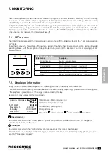
The inverter has 4 optically coupled digital inputs which can be accessed from the communication terminal block. Each digital
input consists of 2 terminals: INi+ and INi- (i = digital input identi
fi
cation number).
The digital input should be controlled using a contact between the INi+ and INi- terminals. Closure of the external contact acti-
vates the digital input.
If the communication ports are activated during the startup wizard, the functions listed in the table will be associated with the
input ports.
Port
Function
Signal on display when command active
IN1
Monitoring of external over-voltage dischargers (SPD)
W07: EXTERNAL SPD FAULT
IN2
Remote power off
A01: EXTERNAL SHUTDOWN ACTIVATED
IN3
Programmable
IN4
Programmable
4.4.2-1
Connection example for the contact signalling external discharger intervention
Access the display menu
SETTINGS > CONNECTIVITY > DIGITAL INPUT
to check or modify the functions assigned to the
programmable digital inputs.
4.4.3. Dry contacts
The inverter has 3 programmable digital inputs for external signalling of its own status.
The digital inputs are supplied as dry contacts on the communication terminal block. Each dry contact consists of a relay with 3
available terminals on the terminal block: Ci, NCi, NOi (i = digital output identi
fi
cation number).
Digital output activation causes the contact between the Ci and NOi terminals to close. If this is not the case, the dry contact
keeps the Ci and NCi terminals short-circuited.
The current and rated voltage permitted by the NCi and NOi contacts is: 2 A, 250 VAC.
The desired function can be assigned to dry contacts via the display menu
SETTINGS > CONNECTIVITY > DIGITAL OUTPUT.
For example, to monitor systems status, it may be useful to set a remote general alarm for the inverter.
Содержание SUNSYS H30
Страница 4: ...4 SUNSYS H30 H30i Ref IOMSUNHMXX04 GB 00 4 ...
Страница 37: ......
Страница 38: ......
Страница 39: ......

