background image

2

SUNSYS H30-H30i

 - Ref.: IOMSUNHMXX04-GB  00

2


Manufacturer's warranty - Warranty on products in the SUNSYS HOME series


Sicon S.r.l., a member of the Socomec group which deals with the supply, control and safety of low voltage electrical networks, with 
registered head office in via Sila 1/3 – Z. I. Scovizze, 36033 Isola Vicentina (VI), guarantees that its products in the Sunsys Home 
series are new and adhere to the applicable technical specifications and quality standards.

1) Conditions of Warranty

Sicon S.r.l.  guarantees its products in the Sunsys Home series for a period of 5 years from purchase, for manufacturing or 
material defects only.

The warranty period runs from the date on which the new product was purchased by the end user at the showroom of an official 
dealer (the reference data is that indicated on the proof-of-purchase document).

The warranty covers: 

a) the free repair or replacement of the product or of the faulty component, but with the expenses for installation of the product 

or of the replacement component borne by the customer or by the end user;

b) sending the faulty product to Sicon S.r.l. (or to authorised centres) with uninstallation, transportation and related expenses 

borne by the customer or by the end user;

  The decision to repair or replace the product or the faulty component will be taken only and exclusively by Sicon S.r.l..

  Replacement or repair of parts and any modifications to the product or components during the warranty period shall not extend 

the duration of the warranty.

  This conventional warranty is intended to supplement - but not replace - all other rights of the product consumer/buyer and, 

in particular, does not affect the rights to which the consumer is entitled under Italian Law Decree 06.09.2005 no. 206 (cd. 
Consumer code).

  Sicon S.r.l. reserves the right to offer extensions to this warranty which must be agreed in writing.

2) Procedure

I. 

The faults must be reported to the After-Sales Service of the Photovoltaic department at Sicon S.r.l. (via Sila 1/3 – Zona 
Industriale Scovizze – 36033 Isola Vicentina - Vi -), or in writing by registered mail, or by email ([email protected]
or fax (+39 0444-598626).


In any case a brief written report must be sent immediately to the aforesaid Department indicating the type of fault, the serial 
number of the product and all the data on its identification plate.


A copy of the product proof of purchase must be attached to the written report (document - delivery note, invoice, cash 
register receipt - stating the date of purchase; said document must contain the data necessary for machine identification - 
model, serial number). Should it be impossible to furnish proof of purchase, the serial number and date of manufacture will 
be used to calculate the probable expiry date of the warranty;


The faulty product may only be returned to Sicon S.r.l. after the return authorisation number has been received, which will 
be issued by the service centres on receipt of the fault report.

II.   The faulty product must be returned to Sicon S.r.l.  in its original packaging or an equivalent, attaching the return authorisa-

tion number.

III.   If the goods are recognised as faulty and under warranty, Sicon S.r.l. shall send the product and/or the repaired or replace-

ment component to the end user at the address supplied by the latter along with the report of the faults or, failing that, to 
the place where the goods were delivered as established in the sales contract.

IV.   The shipment of the replacement product and/or component is at the expense of Sicon S.r.l.

V.  The installation of the replacement product and/or component must be carried out by qualified personnel or by an authorised 

service centre and the respective cost is borne by the customer or by the end user.

VI.   Sicon S.r.l. shall be reimbursed for all activities carried out on products and/or components not recognised under warranty, 

in compliance with the rates and conditions normally applied by the company.

VII.  Sicon S.r.l. reserves the right to supply a different model of product and/or component as long as it offers equivalent perfor-

mance, in cases where the original model - faulty and under warranty - is out of production.

VIII.  If on-site assistance from qualified Sicon S.r.l. personnel is requested, labour costs and travel expenses will be borne by the 

customer/end user, in line with current Sicon S.r.l. rates.

CONDITIONS OF WARRANTY

Содержание SUNSYS H30

Страница 1: ...SUNSYS H30 H30i Installation and operating manual GB Manuel d installation et d utilisation FR Manuale di installazione e uso IT ...

Страница 2: ...ail or by email assistenza socomec com or fax 39 0444 598626 In any case a brief written report must be sent immediately to the aforesaid Department indicating the type of fault the serial number of the product and all the data on its identification plate A copy of the product proof of purchase must be attached to the written report document delivery note invoice cash register receipt stating the ...

Страница 3: ...ing to appearance or construction which do not affect the normal functioning of the product c Requests that do not fall under the rights established by the warranty conditions are not covered by the warranty described herein and in particular requests for the refund of damages for loss of production loss of earnings or due to defects of the product or due to installation or uninstallation costs Co...

Страница 4: ...4 SUNSYS H30 H30i Ref IOMSUNHMXX04 GB 00 4 ...

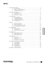
Страница 5: ... 17 4 1 Earth wire connection 17 4 2 Mains connection AC 18 4 3 Photovoltaic field connection DC 19 4 4 Communication port connection 20 5 COMMISSIONING 24 5 1 Startup procedure 24 5 2 Configuration 25 5 3 Protection autotest procedure 26 6 MAINTENANCE 27 6 1 Switching off the inverter 27 6 2 Battery replacement 27 6 3 Disposing of the inverter 28 7 MONITORING 29 7 1 LEDs status 29 7 2 Displayed i...

Страница 6: ...G RISK OF BURNS The outer casing temperature can reach 70 C Hot surfaces may constitute a hazard WARNING RISK OF ELECTRIC SHOCK The inverter may only be opened by authorised personnel for technical assistance purposes Risk of electrocution due to the energy stored in the condensers wait 5 minutes before removing the cover and make sure no hazardous voltage is present WARNING Device with several po...

Страница 7: ...ts for harmonic current emissions equipment input current 16 A per phase EN 61000 3 3 2008 09 Electromagnetic compatibility EMC Part 3 3 Limits Limitation of voltage changes voltage fluctua tions and flicker in public low voltage supply systems for equipment with rated current 16 A per phase and not subject to conditional connection EN 61000 6 2 2006 03 Electromagnetic Compatibility EMC Part 6 2 G...

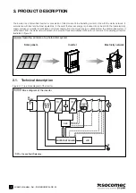
Страница 8: ...d in anticipation of future consumption if not much energy is obtained from the photovoltaic system it will be drawn from the mains network instead to ensure that household utilities continue to run normally The operating principle is illustrated in figure 2 1 2 1 Operating principle of a photovoltaic system 2 1 1 Block diagram of the inverter 1 GFD Ground Fault Detection PV ARRAY RESIS TANCE GFD1...

Страница 9: ...the high efficiency levels the wide voltage range of the PV field and the ability to manage transitory power peaks greater than the rated power supply all help to provide maximum photovoltaic energy in every condition Plus thanks to its high IP class and innovative temperature control the inverter can be placed outdoors To achieve the best performance levels the recommendations provided in this ma...

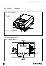
Страница 10: ...re 2 3 1 and the corresponding detailed description is provided in sub paragraphs 2 3 1 to 2 3 2 2 3 1 External inverter features 2 3 1 1 System status information LCD display capacitive keypad LEDS status DC connectors Data plate Cover AC connector Earth connection PE Removable panel LEDS STATUS GREEN YELLOW RED SELECT select page EXIT exit menu ENTER select menu or confirm LCD display ...

Страница 11: ...NG The external earth connection terminal PE must be connected to the earth wire before the power supply is connected 2 3 2 1 Inverter input output interfaces DC input connectors AC output connector Earth connection PE Cable glands for Wi Fi antenna optional Valve anti condensate Cable glands for communication ports ...

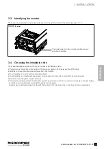
Страница 12: ... outer guard cover to the inverter Warning If any external or internal inverter damage is detected or if any of the packaged accessories are damaged or missing please contact your inverter supplier 3 INSTALLATION 3 1 Before installation Due to the variety of potential user installation environments reading this chapter carefully before installation is strongly recommended All installation and star...

Страница 13: ...here people can come into contact with the equipment easily Mount the unit by fixing it securely to a solid wall The protective panel underneath the right hand part of the guard cover must be removed in order to replace the clock battery access the communication port and update the software as necessary Enough space must therefore be left underneath the inverter so that this side and the connectio...

Страница 14: ...g bracket dimensions are indicated in the figure below Fix the bracket supplied securely to the wall before hanging the inverter on it WARNING Mount it vertically or at a maximum angle of 45 see figure 3 5 2 Be careful as in this case a drop in performance derating may occur due to the deterioration of heat dispersal 259 425 6 569 324 3 5 1 Securing the mounting bracket with screws 3 5 2 Correct a...

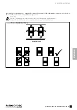
Страница 15: ...stallation or any necessary removal of the product The minimum distances are indicated in figure 3 5 3 WARNING Leave a suitable distance when installing one or more photovoltaic inverter systems Install the photovoltaic inverter in a clean cool room away from direct sunlight 3 5 3 Suitable installation distances X300 300 100 100 200 300 300 1 Dimensions in mm 1 ...

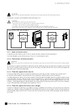
Страница 16: ...the maximum specified PV field short circuit current and voltage levels check the values in the technical data table 3 5 3 Protection against fault currents The inverter is fitted with a unit which monitors and detects fault currents this is sensitive to all types of ground fault current We recommend the application of an external type A 30 mA differential protection device with low sensitivity S ...

Страница 17: ...ld place the operator in a hazardous situation and may damage the equipment WARNING Always observe the rated voltage and current values specified in the design phase of your system It is especially impor tant to observe the maximum voltage and current values for the photovoltaic field see Technical data chapter 4 1 Earth wire connection DANGER Risk of electric shocks from live device parts The inv...

Страница 18: ...ulation diameter not exceeding 12 mm 4 2 1 Connection procedure Take care to perform wiring correctly observing the polarities I Unscrew the connector in three parts A B and C Fig 4 2 1 1 II Run the cable through B and C Strip the wires Secure the wires as indicated below taking care to observe the polarities Insert the earth wire PE corresponding to the relevant symbol Insert the phase wire L cor...

Страница 19: ...rving the polarities Figure 4 3 1 1 illustrates how to connect the positive pole of the photovoltaic field to the corresponding DC connector The negative pole can be connected in the same way 4 3 1 Connection procedure 1 Unscrew the cable gland for the relevant DC connector and run the cable which should have been stripped at the end by approx 15 mm through it 2 Insert the cable into the connector...

Страница 20: ...table below Communication port description Communication ports Quantity Connection type Function RS 485 1 Terminal block D D GND Serial communication interface Micro SD card 1 Micro SD card connector Archiving of past events and statistics USB 1 A type USB connector Firmware updating Dry contacts 3 Terminal block C1 NC1 NO1 C2 NC2 NO2 C3 NC3 NO3 For alarm or machine status indication Digital input...

Страница 21: ...cables must be shielded and guarantee protection of at least 600 V We recommend using shielded multi pole cables with an external diameter between 4 5 and 6 mm The communication cable sleeve should be connected to the inverter earth following the procedure illustrated in figure 4 4 1 1 1 Unscrew the cable gland 2 Remove the protective plug B 3 Run the cable through A and C 4 Strip the cables and f...

Страница 22: ...ion example for the contact signalling external discharger intervention Access the display menu SETTINGS CONNECTIVITY DIGITAL INPUT to check or modify the functions assigned to the programmable digital inputs 4 4 3 Dry contacts The inverter has 3 programmable digital inputs for external signalling of its own status The digital inputs are supplied as dry contacts on the communication terminal block...

Страница 23: ... CONNECTIVITY RS485 PORT The communication terminal block allows connection to one or more inverter units If multiple connection of several inverters is carried out each unit must be assigned a different node number via the display menu SETTINGS CONNECTIVITY RS485 PORT Moreover only the last inverter in the chain must have line termination To disable the termination resistors for the other inverte...

Страница 24: ...hem to direct sunlight The sunlight must be intense enough to produce the required output voltage 2 Measure the no load DC voltage of the photovoltaic panels between the positive and negative poles This voltage must be between 300 and 550 V in direct current DC To check the AC mains network voltage 3 Close the switch on the main switchboard 4 Use an AC voltmeter to measure the no load mains networ...

Страница 25: ...ountry set is the one in which it is installed If it is not or if you want to set the country again contact the technical support centre The startup wizard is used to set system parameters load connection parameters and activate the functions required by the national regulations corresponding to the selected country 5 2 2 General settings The menu SETTINGS GENERAL PREFERENCES can be used to custom...

Страница 26: ...an check whether the following devices have intervened correctly Protection Description V Maximum network voltage limit intervention test restrictive threshold V Minimum network voltage limit intervention test restrictive threshold V Maximum network voltage limit intervention test permissive threshold V Minimum network voltage limit intervention test permissive threshold f Maximum network frequenc...

Страница 27: ...switch before opening the DC disconnection switch DANGER Risk of electric shocks from live device parts The inverter can be connected to two separate power sources DC cable Power from the photovoltaic generator AC cable Power from the mains network supplied by the electricity company Before carrying out any work make sure the electricity sources have been disconnected How to switch off the inverte...

Страница 28: ... 1 Battery inside the inverter 6 3 Disposing of the inverter At the end of its working life the inverter must be disposed of in accordance with local regulations for the disposal of electronic components applicable to the installation site at the moment of disposal ...

Страница 29: ...arnings all LEDs are switched off 7 2 Displayed information During normal operation see paragraph 8 5 Operating statuses the display alternatives are the main screen with readings such as instantaneous power supply daily energy production and operating time the graphical representation of the energy produced during the day Several icons may appear on the main screen 1 Maintenance Mode service icon...

Страница 30: ...howing the energy produced over a specified period can be accessed via the MEASUREMENTS GRAPHICS menu The figure below provides some examples 7 2 1 1 Hourly progress of energy produced over the course of the day kWh 3 0 2 0 1 0 6 12 18 24 h 0 7 2 1 2 Hourly progress of energy produced over the last 7 days 1 1 0 6 kWh 3 0 2 0 1 0 6 12 18 24 h 0 7 2 1 3 Daily progress of energy produced over the las...

Страница 31: ...PHICS COMMANDS INVERTER PROCEDURES ALARMS RESET LED BAR TEST STATISTICS RESET LOAD DEFAULT PARAMETERS AUTOTEST SETTINGS GENERAL PREFERENCES LANGUAGE DATE AND TIME DISPLAY PASSWORD INVERTER SETTINGS COUNTRY CONNECTION PARAMETERS PHOTOVOLTAIC PLANT CONNECTIVITY WIFI SETTINGS RS485 PORT DIGITAL INPUT DIGITAL OUTPUT HISTORY HISTORY LOG V f FAILURE REPORT SERVICE INVERTER INFO FIRMWARE VERSION UPGRADE ...

Страница 32: ...ing devices MicroSD card statistics and past data are continuously saved by the inverter They are therefore always available and can be recalled at any time RS 485 serial port data can be collected by a PC or data logger WiFi Optional communication can take place using devices with a WiFi connection also allowing simple remote monitoring 7 4 1 LOCAL MONITORING REMOTE MONITORING RS 485 Internet web...

Страница 33: ... supplied to the mains network due to voltage frequency outside the range or due to settings made via remote control commands W69 AC Voltage Out Of Tolerance AC mains network voltage outside the tolerance range the inverter waits for the parameter to return to a value within the limits set If the warning persists and the mains network voltage is within the tolerance range contact the Support Servi...

Страница 34: ...is important for the protection of individuals If the alarm persists for no reason make sure the parasitic capacity of the photovol taic system is under 100 nF kWp A04 Insulation Alarm The insulation resistance Riso of the photovoltaic system to earth is insufficient Make sure there is no discharge to earth from the photovoltaic system and that the parasitic capacity of the photovoltaic system to ...

Страница 35: ...cient radiation for connection to the mains network AC Network Check Check electricity mains network parameters fall within the range Insulation Check Check insulation resistance to earth Startup Conditions Check Check for sufficient energy originating from the photovoltaic field Check in progress Check GFCI and test AC output contactors Inverter ON Inverter working properly Inverter OFF due to al...

Страница 36: ...ean efficiency 96 7 Californian efficiency 96 8 Environmental specifications Operating temperature range 20 C 60 C from 40 C to 60 C with possible downgrading Transportation temperature range 25 C 85 C Relative humidity 5 95 without condensation Audible noise 36 dB at a distance of 1 m from the machine Altitude 0 2000 m 0 6666 ft Environmental category in accordance with EN 62109 1 External Mechan...

Страница 37: ......

Страница 38: ......

Страница 39: ......

Страница 40: ...x SOCOMEC Strasbourg 11 route de Strasbourg B P 10050 F 67235 Huttenheim Cedex FRANCE Tel 33 0 3 88 57 45 45 Fax 33 0 3 88 74 07 90 SOCOMEC Isola Vicentina Via Sila 1 3 I 36033 Isola Vicentina VI ITALY Tel 39 0444 598611 Fax 39 0444 598622 it pvconsult socomec com www socomec com IOMSUNHMXX04 GB 00 IOMSUNHMXX04 GB 00 07 2012 ...

Отзывы: