Lit. No. 43755/43757/43873, Rev. 01
12
March 15, 2016
ASSEMBLY INSTRUCTIONS
The spreader shall be installed according to
instructions supplied. Your local outlet is trained to
provide this service and service your spreader with
factory original parts.
1.
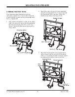
Place the drive assembly on a flat, level surface.
Attach the receiver mount to the drive assembly
as shown below using four 1/2" x 1‑1/2" cap
screws. Tighten the fasteners according to the
torque chart.
MOUNTING THE SPREADER
2. Mount the support frame to the drive assembly
using the six supplied 5/16" x 1" cap screws and
the four supplied 5/16" locknuts. Tighten the
fasteners according to the torque chart.
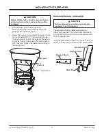
3. Mount the throat support to the support frame
at the 2 lower holes by using the four supplied
5/16" x 1" cap screws and 5/16" locknuts. Tighten
the fasteners according to the torque chart.
5/16" x 1" Cap Screw
Support Frame
5/16" Locknut
Drive Assembly
Receiver Mount
1/2" x 1-1/2" Cap Screw
Throat Support
5/16" x 1"
Cap Screw
5/16"
Locknut
Support Frame


