background image

50 lb. Commercial Spreader 

with Side Spread Control


MODEL # 2150 

ASSEMBLY INSTRUCTIONS 


2150_M51257_RevMar2021


PAGE 1 


Prior to assembly, you will need:  


Needle nose pliers 


#2 Phillips screwdriver 


 Two 7/16

 adjustable or box wrenches 


SIDE SPREAD CONTROL 

Your EarthWay spreader includes a 
patented feature to prevent fertilizer from 
being spread to the left side. To activate this 
feature, slide the lever below the hopper to the back (if 
standing behind the spreader) and position the left wheel 
6

-12

 from your sidewalk or border.  This will not waste 

fertilizer like competitor designs that leave 7X the 
fertilizer inside the wheels from blocking material leaving 
the impeller.  PATENTED USPTO 10,993,368 B2 
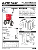
ASSEMBLY HARDWARE 


SPREADER COMPONENTS 


HANDLES 


C

O

N

TR

O

L ROD


H

A

N

D

LE

 S

H

A

FT


GEAR BOX 

IMPELLER 

LO

WE

R

 F

R

A

M

GUAGE 

HOPPER 
FRAME 

X-BRACE 

METER 
ROD 

REST 

AXLE 

PIVOT 

Visit our  

EarthWay 

website to view the 

assembly video 


2

 1/4


2


AGITATOR 

SPACER 

BEARING 

BUSHING 

SCREW 

¼” X 1 ½”


¼” X 2”


¼” X 2 1/4”


LG COTTER PIN 

SM COTTER  

LOCK NUT 

 NUT 

Содержание EV-N-SPRED 2150

Страница 1: ...the hopper to the back if standing behind the spreader and position the left wheel 6 12 from your sidewalk or border This will not waste fertilizer like competitor designs that leave 7X the fertilizer...

Страница 2: ...nd flow rate Do not use powdered materials as it will damage the gearbox Gears are permanently lubricated at the factory Do not open the GEARBOX or dirt may enter IF YOUR SPREADER COMES SEMI ASSEMBLED...

Страница 3: ...NOT TIGHTEN NOTE Numbers on frame brace must be facing toward gear box as shown C Install the FOOT into the FRAME and align the bolt holes in the FOOT and the FRAME a Phillips screwdriver or large nai...

Страница 4: ...adjustable handle for taller operators TALL OPERATOR CONFIGUATION your preassembled handle comes set for the shorter operator position Remove with the four handle holes align the handle shaft with the...

Страница 5: ...Assembly and Operation Instructions 2150_M51257_RevJune2021_new PAGE 5...

Страница 6: ...nd of the PIVOT ROD through the back of the PIVOT ROD BRACKET as shown see below Step 12 Install HANDLE SHAFT to LOWER HANDLEs and PIVOT BRACKET assembly as shown Using 2 bolts and locknuts TIGHTEN BO...

Страница 7: ...preader gauge to 30 inside the hopper move control plate to the full open 1 Open the shut off so that the drop holes are completely open as illustrated to the right 2 Review the Control Lever position...

Страница 8: ...nd spread as normal 4 When you have completed this spreading pass close the control lever to 0 and then open the SideSpread Control by sliding the control lever from back to the front for a FULL 180 d...

Страница 9: ...SCREEN 8 60602 OPERATOR HANDLES ASSEMBLY 2 60332 HOPPER ASSEMBLY KIT 2 1 2 6 9 60333 GEARBOX IMPELLER SHAFT KIT 3 38168 HARDWARE KIT 3 1 3 92 10 12110 IMPELLER 4 60268 CONTROL KIT X BRACE KIT 4 1 4 5...

Отзывы: