background image

Lit. No. 43755/43757/43873, Rev. 01 

13 

March 15, 2016

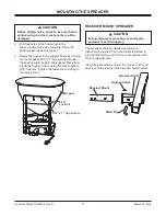
RECEIVER MOUNT SPREADER

The spreader shall be installed according to 

instructions supplied. Your local outlet is trained to 

provide this service and service your spreader with 

factory original parts.

Insert the assembled unit into the receiver hitch and 

secure with the supplied hitch pin and hairpin cotter.

MOUNTING THE SPREADER

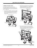
4.  Drill four holes in the hopper using the 

support frame holes as a template. Place the 

backing plate inside the hopper.

5.  Fasten the hopper to the support frame by running 

the four supplied 5/16" x 1" cap screws through 

the backing plate, hopper and support frame from 

inside the hopper. Attach using the four supplied 

5/16" locknuts. Tighten the fasteners according to 

the torque chart.

5/16" x 1" Cap Screw

5/16"

Locknut

Hopper

Hairpin Cotter

Hitch Pin

Receiver Mount

Receiver Hitch

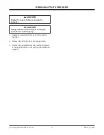
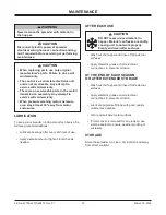
 CAUTION

During removal or mounting, securely grip 

spreader to avoid dropping.

 CAUTION

Before drilling holes, check to be sure that no 

vehicle wiring or other components could be 

damaged.

Содержание SR-210

Страница 1: ...Rev 01 SR 210 Wireless Tailgate Spreader Owner s Manual and Installation Instructions Original Instructions This manual is for SnowEx wireless tailgate spreaders with serial numbers beginning with 15...

Страница 2: ......

Страница 3: ...ly Instructions 12 Receiver Mount Spreader 13 ELECTRICAL DIAGRAM 14 OPERATING THE SPREADER 15 Driving and Spreading on Snow and Ice 15 Ensuring the Spreader has Power 16 Starting and Stopping Motor 16...

Страница 4: ......

Страница 5: ...those specified in this manual Warranty Registration Follow the directions on the SnowEx Warranty Registration and Customer Survey form included in the spreader literature kit The registration form i...

Страница 6: ...NG CAUTION LABELS Please become familiar with the Warning and Caution labels on the spreader NOTE If labels are missing or cannot be read see your sales outlet CAUTION Indicates a potentially hazardou...

Страница 7: ...ATION SERIAL NUMBER LABEL Code Definition YY 2 Digit Year MM 2 Digit Month DD 2 Digit Day LL 2 Digit Location Code XXXX 4 Digit Sequential Number ZZZZZZ Assembly Part Number Model No 00000 Serial No Y...

Страница 8: ...RNING Driver to keep bystanders minimum of 25 feet away from operating spreader Before working with the spreader secure all loose fitting clothing and unrestrained hair Before operating the spreader v...

Страница 9: ...ive gases which can cause personal injury Therefore do not allow flames sparks or lit tobacco to come near the battery When charging or working near a battery always cover your face and protect your e...

Страница 10: ...0 49 4 55 2 75 3 85 0 M6 x 1 00 M12 x 1 75 M8 x 1 25 M14 x 2 00 M10 x 1 50 M27 x 3 00 M22 x 2 50 M30 x 3 50 M24 x 3 00 M20 x 2 50 11 1 19 5 38 5 67 107 7 7 613 778 1139 1545 450 428 562 796 1117 M33 x...

Страница 11: ...proper vehicle applications CERTIFICATION WARNING Overloading could result in an accident or damage Do not exceed GVWR or GAWR as found on the driver side cornerpost of vehicle WARNING New untitled ve...

Страница 12: ...ghten the fasteners according to the torque chart MOUNTING THE SPREADER 2 Mount the support frame to the drive assembly using the six supplied 5 16 x 1 cap screws and the four supplied 5 16 locknuts T...

Страница 13: ...he support frame holes as a template Place the backing plate inside the hopper 5 Fasten the hopper to the support frame by running the four supplied 5 16 x 1 cap screws through the backing plate hoppe...

Страница 14: ...ess Receiver Module Connections Spreader Power Plug End Battery Negative Battery Positive Bypass Common Learn Antenna LED Motor Positive Motor Negative Battery Power Positive Terminal 4 Black Wire Bat...

Страница 15: ...l You can have a serious or even fatal collision if you drive after drinking Please do not drink then drive or spread ice control materials Here are some tips for driving in these conditions Drive def...

Страница 16: ...ver shall verify that all bystanders are a minimum of 25 feet away from operating spreader 4 Unplug the spreader push the toggle switch into the center position and then replug the spreader The spread...

Страница 17: ...Remove the hitch pin from the receiver hitch 3 Remove the spreader from the vehicle and stand in an upright position This may require additional support CAUTION During removal or mounting securely gr...

Страница 18: ...r from the vehicle to pair and program the wireless key fob control Begin by unplugging the spreader from the 7 way plug 2 Push the toggle switch DOWN into the MANUAL OVERRIDE position 3 Plug the spre...

Страница 19: ...uence 50 OFF 100 50 OFF 100 The sequence must be completed before the blue light stops flashing Light Button Pairing the Wireless Key Fob Control to the Wireless Control Module 1 Check that the wirele...

Страница 20: ...ny reason use silicone sealant to ensure weather proofing of enclosure STORAGE Store the spreader in a clean dry location and away from direct sunlight WARNING Never remove the spreader with material...

Страница 21: ...otor contact distributor Loose connection Corrosion Test direct power 12 volts to motor Load test battery Replace all corroded connections Apply dielectric grease Material issue Too much amp draw Bad...

Страница 22: ...to spreader Ignition off Spreader does not respond to key fob Turn ignition on Remove cover and check all connections Material obstruction Range issue Clear obstruction Fully seat power connector No v...

Страница 23: ...he equipment off and on the user is encouraged to try to correct the interference by one or more of the following measures Reorient or relocate the receiving antenna Increase the separation between th...

Страница 24: ...es the right under its product improvement policy to change construction or design details and furnish equipment when so altered without reference to illustrations or specifications used TrynEx Intern...

Отзывы: