93
Scope and Multimeter Operations
M4 Scope Module Pairing
8.2 M4 Scope Module Pairing
When the M4 Scope Module is connected either by USB cable or in it’s docking station on the rear
of the diagnostic tool, it automatically pairs with the diagnostic tool using the USB connection.
z
To check the paired status of the M4 Scope Module:
1. Select
System Settings
>
Paired Devices
.
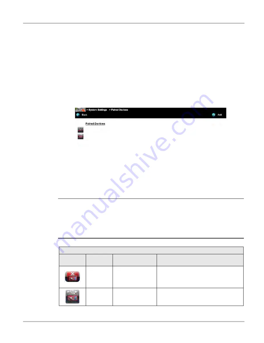
The paired devices screen opens (
The Paired Devices screen lists all of the devices paired to the diagnostic tool, and also indicates
whether or not there is active communication occurring.
The M4 Scope Module will be listed as SCOPE MODULE M4 or similar.
Figure 8-3
Typical Paired Devices screen
8.2.1 M4 Scope Module Hardware Status Indicators
The Hardware Status indicators in the lower-right corner of the Home screen provide a quick
reference to the M4 operation status. The background color of the status indicator icon represents
the condition of the connectivity. Icon status is shown in the table below:
NOTE:
i
When the M4 is connected into it’s docking station on the rear of the diagnostic tool or is
connected to the diagnostic tool with a USB cable remotely, the M4 USB connection status
indicator (lower right of screen) is displayed. When the M4 is removed from the docking station,
and is not connected by a USB cable the status indicator background displays red with an “X”.
When the M4 is actively being used in the Scope Multimeter function the background displays
green (not shown in chart below).
4$01&.0%6-&.
4$"/.0%6-&
M4 Scope Module Connection Status Indicator
Icon
Background
Color
Condition
Action/Indication
Red
Not Connected/Not
Paired
Connect the M4 to the docking station on the
rear of the diagnostic tool or (if using remotely)
connect the M4 to the diagnostic tool with a
USB cable.
Grey
Connected/Paired
Indicates the M4 is connected to the docking
station on the rear of the diagnostic tool or (if
using remotely) is connected with a USB cable.


