16
Snap-On EEWH329A
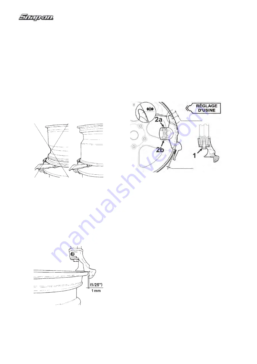
Angular tool adjustment
(Fig. 4.1-4a)
The tool is adjusted at the factory with an optimal an-
gle for most wheels used today. However, the angle
can be optimised for wheels with a diameter that
differs considerably from the standard.
To adjust the tool angle, proceed as follows:
1
Mount the rim for which the adjustment is required
.
2
Loosen the lower screw (
1
).
3 Adjust the tool with the screws shown (
2a
and
2b
). Unscrew the screw
2a
or
2b
to rotate the tool,
respectively clockwise or counterclockwise.
4 Screw in the opposite screw to block the tool in the
desired angular position.
5 Tighten the lower screw (
1
) with a torque of 35 Nm
.
Ø 17"
1/25"
(
1 mm
)
2/3"
(
17 mm
)
Ø 20"
Fig. 4.1-4a
NOTE:
YOUR MACHINE IS SHIPPED WITH SEVERAL
REPLACEMENT PLASTIC INSERTS (INSIDE STANDARD
EQUIPMENT PACK). THE PLASTIC INSERTS WILL
HELP AVOID DAMAGE FROM ACCIDENTAL CONTACT
BETWEEN THE MOUNT/DEMOUNT HEAD AND THE
RIM. THE PLASTIC INSERTS WILL NEED TO BE
PERIODICALLY REPLACED.
MAINTENANCE NOTE:
IF THE MOUNT/DEMOUNT HEAD NYLON INSERTS
ARE WEARING OUT PREMATURELY, THE CAUSE
IS THE OPERATOR’S FAILURE TO CORRECTLY
SET THE RIM DIAMETER ADJUSTMENT KNOB,
CAUSING THE INSERT TO INCORRECTLY
CONTACT THE RIM.
NOTE: ONCE THE MOUNT/DEMOUNT HEAD IS
POSITIONED PROPERLY, IDENTICAL WHEELS
MAY BE CHANGED WITHOUT HAVING TO RESET
THE HEAD.
F.
Insert the mount/demount tool between the bead
and the mount/demount head. Pry the bead onto the
mount/demount head using the mount/demount head
C.
Set the rim clamps to the proper position: retract
clamps to clamp the wheel from the outside and expand
clamps to clamp from the inside.
When clamping small wheels (14” or smaller) from
the outside, set the clamps at a diameter nearly equal
to the rim diameter before placing the wheel on the
clamps. This will help avoid the possibility of pinching
the tire as the clamps retract.
NOTICE !
TO MINIMIZE THE RISK OF SCRATCHING ALLOY
OR CLEAR COATED RIMS, THESE RIMS SHOULD
BE CLAMPED FROM THE OUTSIDE.ô:
D.
Liberally lubricate both beads. Place the wheel
WITH DROP CENTER UP
(Fig. 4.1-3a) on the
turntable, and clamp in position. It may be necessary to
hold the tire and wheel down while clamping to insure
contact between rim and clamp as shown in 4.1-3a.
331
Fig. 4.1-3
Fig. 4.1-3a
E.
Gently position the mount/demount head in contact
with rim edge, now manually push the lock lever up
and lock it into place. The mount/demount head
automatically moves vertically up and away from
the rim edge. Turn the swing arm adjustment knob
clockwise until the mount/demount head moves
horizontally away from the rim fl ange by approximately
1/16” (2mm): this is necessary to avoid any rim contact
during the changing process. (Fig. 4.1-4).
332a
Fig. 4.1-4
Содержание EEWH329A
Страница 25: ...25 Snap On EEWH329A Blank Page ...
Страница 28: ...28 Snap On EEWH329A ...
Страница 51: ...51 Snap On EEWH329A Page blanche ...
Страница 54: ...54 Snap On EEWH329A ...
Страница 77: ...77 Snap On EEWH329A Página en blanco ...


