


Installation
a)
Check the contents of the package:
Component
Quantity
Keyswitch Interface
assembly (red / blue)
1
Earth Strap
1
Operating Key
2
Opening Key
1
Long Screw
2
Instruction leaflet
1
Blue Back box
supplied with Blue
keyswitch interface
assembly
1
b)
The keyswitch assembly may be mounted on a standard
electrical box or on the backbox.
c)
Feed the fire rated cables through the entry holes and
mount an electrical box or the red/blue back box to an even
wall surface using suitable fixing.
"
When semi flush fixing the keyswitch
assembly a standard electrical box must first be flushed
into the wall before the keyswitch assembly is fitted.
d)
Terminate each cable entry at the back box. Use the
earth
strap
or the
earth point
in the back box to maintain loop
cable earth continuity. Connect the loop cable to the
terminals.
e)
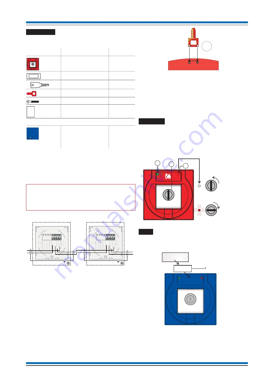
Disengage front cover from the keyswitch assembly using
the end of the opening key 'E' and lift out the cover from the
bottom edge.
f)
Secure the keyswitch assembly to the back box using the 2
long screws supplied.
g)
Hook the front cover onto the top edge of the keyswitch unit
and then push the bottom edge down until it click shut.
Check both hooks on the top of the front cover are locked
onto the keyswitch assembly.
Operation
To operate the keyswitch insert the operating key into the
keyhole 'J' and turn clockwise to the stop position, the red LED
'K' is flashing. The green LED 'I' gives an operating indication.
Apply the reverse procedure to return the keyswitch to a normal
operating position.
Label
When using the blue keyswitch interface to control plant ensure
the unit is labelled to describe what is being controlled by the
keyswitch.
It is suggested that an A4 sheet white paper label
32 x 12mm is used, such as the one from RS, part number
RS495 385. The required text can be printed onto the label. The
label is stuck centrally inside the aperture behind the transparent
cover. Ensure LEDs remain visible and are not covered by the
label.
Installation instructions
38
E
i
THIS WAY UP
1I
N
2O
U
T
4
C
Keyswitch assembly
Loop
In
Loop
In
1I
N
2O
U
T
3
4
C
Keyswitch assembly
Loop
Out
Loop
Out
3
I
J
K
Normal
Active
O
I
O
I
O
I
Disable
Zone n
32 x 12mm
stick on label
Transparent cover
Содержание SenTRI
Страница 49: ...Notes 49 SenTRI ONE System...
Страница 50: ...Notes Installation instructions 50...
Страница 51: ...Notes 51 SenTRI ONE System...