SMS SenTRI Скачать руководство пользователя страница 35

Manual Call Points

Options

¨

Manual Call Point (Glass)

¨

Manual Call Point (Glass) with Protective cover

¨

Manual Call Point (Resettable element)

¨

Manual Call Point (Resettable element) with Protective
cover

¨

Weatherproof Enclosure for MCP

Glass or Resettable element options
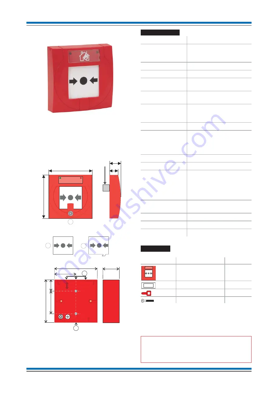
Optional Back box

The optional back box has recessed centres 'D', 3 at the top and
1 at the bottom, a maximum of 2 are usable.

Technical data

Standard

EN54: Part 11: 2001

Dimensions

height 88 mm x width 88 mm
depth 21 mm or 57 mm
when surface mounted

Full assembly weight 110g - approximate

Storage temperature -30 to 70ºC

Operating
temperature

-25 to 70°C

Relative Humidity
(Non condensing)

up to 95%
Temperature 25 to 55°C

Emission

BS EN61000-6-3:2001
Residential, Commercial &
Light Industry

Class B limits

Immunity

BS EN50130-4: Part 4 :1996

Ingress Protection

IP43 estimated standard type
IP55 estimated with
protective cover and back
box

Colour

Red (similar to RAL3020)

Case

ABS engineering plastic

Indicators

Normal

Active

Green LED for status and
find device application
Red LED and Yellow tab for
active or Fire indication

Testing

The operation of the MCP is
tested by using a test key

Terminals

2.5mm

2

maximum

LPCB Approved

SEN-800

Operating voltage

35V to 41V

Installation

a.

Check the contents of the package:

Component

Quantity

Call point assembly

1

Earth Strap

1

Test Key

1

Long Screw

2

b.

The call point assembly may be mounted on a standard
electrical box or on the optional red back box SEN-895.

c.

Feed the fire rated cables through the entry holes and
mount an electrical box or the red optional back box to an
even wall surface using suitable fixing.

"

When semi flush fixing the call point assembly

a standard electrical box must first be flushed into the
wall before the call point assembly is fitted.

35

SenTRI ONE System

87

87

C

15

21

Removable
Terminal block

A

Glass

Top

B

Resettable element

Top

36

THIS WAY UP

50

88

43,5

18,5

D

D

88

Содержание SenTRI

Страница 1: ...4188 979_Issue 2_04 10 SentriONE installation Part of Document pack 2534 235_issue 2 Data and Installation Instructions SenTRI ONE panel based fire detection and alarm system 042bc 14 one...

Страница 2: ...oop circuit 20 Master alarm circuits 21 Common Fault contacts 21 Fire Output contacts 22 Repeat indicator panel 22 External Evacuation input 23 Class Change input 23 RS232 Port 23 USB Port 23 Battery...

Страница 3: ...arts 46 Control Panels 46 Printer 46 Repeat panels 46 T Breaker and Remote LED 46 Manual call points 46 Keyswitch interface 46 SenTRI Analogue Sensor Sounder and Strobe units 47 Beam sensor 47 Sounder...

Страница 4: ...ion to prevent damage to the equipment or a warning to inform of dangerous conditions that may result in injury or death Abbreviations ac Alternating current AS Anti surge C Common CH Channel dc Direc...

Страница 5: ...2002 The cables must be installed using cable manufacturers recommended fixing and accessories Fire sensor cover Each fire sensor may be supplied with a plastic dust cover The cover must be fitted to...

Страница 6: ...ey mustnot run together for example either close to the Control Panel or in a service duct There should be as much physical separation as possible between the cables and the mechanical protection of t...

Страница 7: ...le A maximum of 1Km cable distance is allowed between Control Panel and Repeat indicator panel Belden No 9842 EIA RS485 Applications O A Beldfoil Braid having two twisted pairs Loop cable A loop cable...

Страница 8: ...on Load factor per device Maximum devices per loop SENTRI RPT Repeat panel loop powered 3 4 SENADV IP ST XX Low profile range Strobe Red 10 100 SENADV SN X low profile range SENADV IP SN X low profile...

Страница 9: ...Interface 1 4 127 127 78299 01NM Tee breaker 0 5 127 The maximum devices per loop and load factor per device have been revised due to changes in product specification A maximum of up to 100 input chan...

Страница 10: ...em Devices Manual Call Point T Breaker T End of Line Unit Magnetic door release Conventional Products off interface inputs Alarm sounder Conventional Fire Detector Manual Call Point Loop circuit T 4 I...

Страница 11: ...loop fire control panel Up to 127 addressable devices can be connected to a loop circuit devices like sensors call point and interface units Two master alarm circuits RS485 Port to connect to repeat i...

Страница 12: ...ately on occurrence of a Fault event The relay is normally energised Master alarm circuits and fuses 2 Master alarm circuits operating at 24 volt nominal 200 mA maximum per circuit MA1 Fuse FS2 250mA...

Страница 13: ...cement or equivalent type battery as there is a risk of an explosion if incorrect battery is used Power supply Standard Designed to EN54 4 1997 Mains supply voltage and fuses 230V 50Hz protected by FS...

Страница 14: ...and Log book 1 part supplied in a plastic bag fitted to the enclosure How to disassemble the panel to gain access to the Backbox a Open the two captive screws k on the Outer cover j using the allen ke...

Страница 15: ...mount the backbox onto a flat wall using suitable fixings 15 SenTRI ONE System Floor level Master Alarms 2 Cable entry points 13 Top 2 Back 3 Panel fixing points top hole is a keyhole 1 7m Fault Relay...

Страница 16: ...the upper part k of the module into the backbox and then secure the assembly by tightening the two captive screws l using the allen key Ensure the two PCB fixing screws m that provides earth bonding a...

Страница 17: ...tests WITH THE CABLES CONNECTED to the panel and system device terminals Such a test may damage the electronics circuitry in loop devices and at the panel 17 SenTRI ONE System GLAND GLAND BOARD EARTH...

Страница 18: ...ALARM DO NOT SWITCH OFF The fire alarm equipment s fused spur unit must be fed from a dedicated switch or protective device at the local mains supply distribution board Mains and battery supply connec...

Страница 19: ...DISABLE COMM TOOL P11 RL1 RL2 RED RED RL3 RL4 VE 0V DRN PP10 RX TX 0VISO DRN ISOLATED RS232 NC C NO DRN COMMON FAULT PP4 DRN FIRE OUTPUT PP5 EXT EVAC PP8 VE 0V DRN CLASS CHANGE PP9 L1 0V DRN LOOP END...

Страница 20: ...t cover more than the equivalent of one zone as defined in BS5839 Part 1 As every device has a loop isolator the application of more than 32 devices does not require any special consideration Ensure t...

Страница 21: ...ered from an independent power supply where required 21 SenTRI ONE System MA1 FS2 250mA MA2 FS3 250mA MAIN CONTROL BOARD PANEL 10K Ohms End of line resistor fitted in the last alarm sounder Convention...

Страница 22: ...NELS can be connected directly to the fire panel to its RS485 Port The furthest repeat indicator panel can be installed a maximum of 1Km cable distance away from the fire panel The factory default set...

Страница 23: ...nfigurable modes of operation and baud rate which are set during the commissioning of the system The configurable modes include standard default printer universal or Ascom The ports can be used to con...

Страница 24: ...ssembly open b Connect the batteries in the manner illustrated m ensuring one of the connection is left disconnected Then fit the batteries inside the enclosure as illustrated n c Fit the connector of...

Страница 25: ...ter cover by hooking it over the top edge j of the backbox and then close the bottom of the outer cover k onto the backbox and secure the cover by the captive screws using the allen key All the remain...

Страница 26: ...ly Belden No 9842 EIA RS485 Applications O A Beldfoil Braid 1Km maximum cable distance from the control panel to the last repeat indicator panel must have following characteristics Two twisted pairs 2...

Страница 27: ...S4 BASE GASKET can be fitted to the base to prevent water damage from dripping water from the ceiling Base labels An optional label SEN BASE LABEL can be fitted to the base The label can be marked up...

Страница 28: ...ssible to connect a conventional Manual Call Point non UK application only with a series resistor of value 470 Ohms coupled with an end of line 10Kohms resistor In this case the fire input is fully mo...

Страница 29: ...base and rotate it again until it clicks and goes no further the lines on the base and SenTRI device will align To fit a dust cover Place the dust cover onto the tool inside the cradle Offer the cover...

Страница 30: ...Cut a 140mm diameter hole in the ceiling tile If required use a Bi Metal Holesaw 140mm or 146mm from www shop4tools co uk Insert the semi flush shroud assembly into the hole in the ceiling tile Hold...

Страница 31: ...0 to 70 C Operating temperature 0 to 50 C Relative Humidity Non condensing up to 95 Temperature 5 45 C Emission BS EN50081 1 1992 Part 1 Residential Commercial Light Industry Class B limits Immunity B...

Страница 32: ...junction box c Secure the angle bracket assembly onto the junction box using the gasket and angle bracket fixings d The applicable sensor head may now be fitted to the base assembly by twist and lock...

Страница 33: ...ues with measurement taken at 90 anechoic fast response Low profile 100dBA 3dBA System 103dBA 3dBA Standard sounder only EN54 Part 3 Messages Tones and Strobe flash rate see instructions supplied with...

Страница 34: ...a terminal block to which loop cables are connected Installation instructions 34 LC 0C L1 01 L2 02 LC 0C L1 01 main assembly L2 02 base Sounder Strobe device 3 way red black red black red black Loop...

Страница 35: ...mated with protective cover and back box Colour Red similar to RAL3020 Case ABS engineering plastic Indicators Normal Active Green LED for status and find device application Red LED and Yellow tab for...

Страница 36: ...he tab to position F and insert the glass A or optional resettable element B h Hook the front cover onto the top edge of the call point assembly and then push the bottom edge down until it click shut...

Страница 37: ...g temperature 25 to 70 C Relative Humidity Non condensing Temperature 25 55 C up to 95 Emission BS EN61000 6 3 2001 Residential Commercial Light Industry Class B limits Immunity BS EN50130 4 Part 4 19...

Страница 38: ...using the 2 long screws supplied g Hook the front cover onto the top edge of the keyswitch unit and then push the bottom edge down until it click shut Check both hooks on the top of the front cover ar...

Страница 39: ...The SenTRI interface modules can be mounted in other equipment housings using the DIN rail mount brackets A module can also be fitted into a plastic box or metal box The boxes have cable termination...

Страница 40: ...Can be configured as LED output The cable screens must be connected to an on the chassis or in the metal box If a module is mounted on a then the DIN rail must electrically connected to the earth ter...

Страница 41: ...k with or without a delay Input channel can be configured as a switch input of Fire Fault Supervisory non fire or Confirmation signal with input acceptance delay of up to 10 seconds for a Fire input a...

Страница 42: ...including surface mount and DIN rail mount EN54 17 2005 and EN54 18 2005 Cables Any suitably rated cable may be used for wiring the output lines to drive the required load For information on cables re...

Страница 43: ...condensing Emission BS EN 61000 6 3 2001 Residential Commercial Light Industry Class B limits Immunity BS EN50130 4 1996 Part 4 LVD BS EN 60950 2002 Ingress Protection Metal box IP40 estimated Colour...

Страница 44: ...2 12V 2 1Ah sealed lead acid batteries Input zone channels 2 wire inputs for conventional zone circuits Circuits are monitored for Detector fire MCP fire Wiring open circuit fault Wiring short circui...

Страница 45: ...ls h Connect the transformer secondary wires to terminal block P7 on the interface board i Place the batteries inside the back box however do not make the connection this is done during commissioning...

Страница 46: ...SENTRI RPT Repeat panel EN54 SENTRI RPT BATT Battery pack for Repeat panel for SENTRI RPT T Breaker and Remote LED 78299 01NM T Breaker to create a spur circuit off the main loop SEN LED Remote LED m...

Страница 47: ...TRI Removal tool SEN COVER REMOVER SenTRI Dust cover remover tool spare adaptor SEN BASE LABEL SenTRI Label plate pack of 50 Beam sensor SENTRI BEAM SenTRI Beam sensor pair SEN 741 01 Angle bracket wi...

Страница 48: ...ox Medium Voltage Mains powered interface unit S4 78302 02NM S4 Mains Powered Interface Unit 4 Channel mains powered interface 78301 01NM Mains powered fire alarm interface require batteries 19104 52...

Страница 49: ...Notes 49 SenTRI ONE System...

Страница 50: ...Notes Installation instructions 50...

Страница 51: ...Notes 51 SenTRI ONE System...

Страница 52: ...of via a suitable recycling centre and in accordance with national or local legislation Do not dispose of with your normal household waste Do not burn WEEE Directive At the end of their useful life t...

Отзывы: