background image

1.

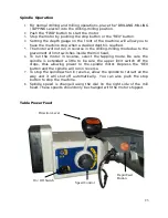
The X axis power feed motor is powered by it's own motor. To turn the
power feed on, move the ON /Off switch to the on position.

2.

Turn the speed control to zero before moving the direction lever. This
will keep the table from moving faster than desired.

3.

Move the direction lever left to move left and right to move right. The
center position shuts the motor off and disengages the internal gears
so the table can be moved with the hand wheel.

4.

Turn the speed control slowly until you reach the desired feed speed.

Spindle Power Feed

1.

The spindle power feed is located on the mill head. There is a selector
on the right front of the mill head that will select the different feed
speeds. Between each feed speed is a neutral position.

2.

These speeds are best changed with the main spindle motor running.

3.

To   engage   the   spindle  feed,   the   handles   that  are   used  to   manually
move the spindle can also be pulled outward and to the right. This will
engage the spindle feed. To stop the spindle feed, push the handles
inward toward the mill head and to the left.

Changing Spindle Speed 

1.

Turn the power off.

2.

To select the proper speed, move the handle to the desired position. 

3.

If the gear is not engaged, remove the arbor bolt cover. Rotate the
spindle slightly to engage the gears, and then replace the arbor bolt
cover.    

4.

Recheck the handle setting, and then turn the power on. 

24

Содержание MI-409MZ

Страница 1: ...Smithy MI 409MZ Operator s Manual 1 ...

Страница 2: ...otherwise without prior written permission of Smithy Ind For information on getting permission for reprints and excerpts comments or suggestions contact info smithy com While every precaution has been taken in the preparation of this manual Smithy Ind shall not have any liability to any person or entity with respect to any loss or damage caused or alleged to be caused directly or indirectly by the...

Страница 3: ...nual Shop Safety Rules Machine Operation Safety Rules Chapter 3 Machine Specifications Chapter 4 Setting Up Your Machine Overview Preparation For Mounting You Machine Lifting Your Machine Placing it on a stand Chapter 5 Inventory Check a Overview Chapter 6 Machine Overview Overview Major Features Identified Operators Panel 3 ...

Страница 4: ...tions Table power feed Spindle power feed Changing spindle speeds Chapter 10 Speeds Feeds Powerfeeding Overview Speeds Feeds Defined Setting Spindle Speeds Setting Feed Rates Chapter 11 Tapping operation Chapter 12 Tooling Installation Work Holding Chapter 13 Diagrams Parts Listing IN WORK Chapter 14 Electrical Diagrams High Voltage Diagrams Low Voltage Diagrams Changing Input Voltage 110 to 220 o...

Страница 5: ...ine works you risk injury to yourself or others Misuse can cause damage to the machine or to your project To learn more about general machining practices you can turn to a number of sources The Smithy website has a series of Machinist Training Videos under the Machining Helps section of website heading Smithy also offers books that meet the needs of Congratulations on the purchase of your Smithy M...

Страница 6: ...chnicians are available Monday through Friday from 8 00 am to 5 00 pm Eastern Standard Time You can also e mail your questions 24 hours a day to info smithy com Customer Information Please record the information below about your Smithy machine Having this information readily available will save time if you need to contact Smithy for questions service accessories or replacement parts Model Number _...

Страница 7: ... Symbols Used In This Manual In this manual the symbols below draw attention to specific operating issues CAUTION Potential hazard unsafe situation or potential equipment damage that may result in injury to yourself or damage to your machine DANGER Hazardous situation which if not avoided could result in series injury or death WARNING Potential hazard unsafe situation or equipment damage could res...

Страница 8: ... can handle Understand the hazards of operating a machine tool In particular remember never to change speeds or setups until the machine is completely stopped and never operate it without first rolling up your sleeves 2 Wear proper clothing Avoid loose fitting clothes gloves neckties or jewelery that could get caught in moving parts If you have long hair tie it up or otherwise keep it from getting...

Страница 9: ...aying attention to what you are doing and avoiding distractions you will spend many safe enjoyable hours in your workshop 11 Never leave your machine running unattended Attention Machine Operation Safety Rules 1 Stop the machine before servicing Stop the machine before making changes removing debris or measuring your work 2 Don t over reach Don t reach over the machine when it s operating Keep you...

Страница 10: ...peed 8 Do not change the direction of the spindle rotation or lead screw rotation while your machine is running Changing the rotation direction of the spindle or lead screw while your machine is running could cause serious damage to your machine 9 Do not stop the spindle by hand Always use your on off switch to stop the spindle from rotating 10 Do not clear chips by hand Metal chips are very sharp...

Страница 11: ...20 volt Connection Type Plug Cord SPINDLE MOTOR SPECIFICATIONS Horse Power 2 HP 1500 Watts Motor Voltage 220 v adaptable to 110 volts Motor Current A C Motor Amperage 20 Amps 9 7 Amps Motor Type A C Constant Speed Induction PRODUCT DIMENSIONS Weight 966 lbs Depth 34 Width 53 Height 56 Footprint 25 x 16 SHIPPING DIMENSIONS Shipping Weight 1077 lbs Depth 39 Width 40 Height 50 Content Machine Type Wo...

Страница 12: ...ill Diameter 3 X Axis Travel 30 Y Axis Travel 7 25 Spindle Taper R8 Spindle Speeds 95 175 310 450 850 150095 175 310 450 850 1500 Spindle to Table Distance 2 5 to 16 5 Spindle Center to Column 10 Dial Calibration Drill Coarse Feed 045 Dial Calibration Mill Fine Feed 001 Dial Calibration X Axis 001 Dial Calibration Y Axis 001 Powerfeed X Axis Yes Powerfeed Z Axis Yes Spindle Oiled Gear Boxes Yes Oi...

Страница 13: ...he headstock is as low as possible and locked before moving machine 3 Don t mount the machine in direct sunshine in order to avoid heat expansion resulting in the deformity of machine and the loss of accuracy 4 Mount machine to a sturdy table or a solid concrete foundation Smithy s 80 055 with optional chip tray item 80 056 has through holes drilled to accommodate the hole pattern of the MI 409MZm...

Страница 14: ... moving it 8 Attach appropriately rated chains or tow ropes to the machine and hook them to the mechanical lifting device 9 Slowly lift the machine slightly off the pallet to see if the machine is properly balanced If machine is not balanced lower the machine back to the pallet and reposition the chains or tow ropes until a good balance is achieved 10 Once the machine is balanced slowly lift the m...

Страница 15: ...essary to return the machine to Smithy the inventory will ensure that all the parts you received have been returned along with the machine A third reason to perform an inventory is to become familiar with the names of all of the parts of your Smithy machine Check your machine and all packages against the packing slip that was attached to the outside of the machine shipping crate Please advise us a...

Страница 16: ...iew Overview This chapter will help to familiarize yourself with the Smithy MI 409MZ Milling Machine The figure below identifies the major controls for your machine MAJOR CONTROLS 16 1 17 11 2 3 4 5 6 7 8 9 10 12 13 14 15 16 ...

Страница 17: ...ANUAL MODE Use to do a precise feed of the spindle in the manual mode 4 CRANK FOR RAISING AND LOWERING MILL HEAD 5 X Axis manual feed handle 6 Y Axis lock 7 X Axis lock 8 Y Axis manual feed handle 9 X Axis powerfeed selector 10 X Axis rapid feed button 11 Depth stop 12 Quill depth lock 13 Z Axis powerfeed speed selector 14 Control panel 15 Depth gauge 16 Oil site gauge 17 Digital readout for spind...

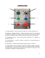
Страница 18: ...g C Forward run button Use for running the mill spindle in a clockwise or forward direction D Reverse Button Used for running the spindle in a counterclockwise or reverse direction E Stop Button Stops the spindle without killing power to machine F E Stop Button turns the power on and off to machine Rotate the button clockwise until it pops out to start the power The power light will illuminate Pus...

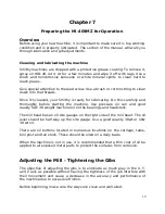
Страница 19: ...ing the machine Use pressure oil can and good quality SAE 30 weight machine oil on the bearings and headstock The mill head has an oil site gauges on the right side of the mill head The oil level should be half way up the site gauge Use a good quality 30wt or 10w 30 wt oil There are oil buttons located in numerous locations on the carriage table tool post and tail stock These should be oiled on a ...

Страница 20: ...g the right screw a little bit of a time to make it tighter When you fill drag on the hand wheel that s the time to stop and tighten the other screw on the left You tighten both screws to hold the device Y Axis Gib Adjustment There are also two adjustment screws One in the front and the other one on the back end which also shown in the image below To loosen the gib for Y axis screw out the front s...

Страница 21: ...initial run in procedure at the factory before the machine is packaged for shipment 1 Once you have your mill setup Smithy recommends that the spindle motor be run for about 5 minutes at each of the spindle speeds starting with the slowest speed 2 Operate the powerfeed motor for the X and Y power feeds for 5 minutes in each of the 6 speeds 3 When the machine has set for some period of thin without...

Страница 22: ...esired height is reached tighten the locking bolts to avoid vibration 2 Head may be rotated 45 in either direction Loosen the three lock nuts Adjust the head to the desired angle and then tighten the heavy duty head lock nuts 3 Move the table from side to side by using the longitudinal handwheel and from front to back by using the cross handwheel 4 Adjust the positive depth stop gauge according to...

Страница 23: ...imit switches inside the mill head 6 To run the motor in reverse select the tapping mode Be sure the spindle is extended a little to be sure the upper limit switch off the stops thus allowing power to the spindle motor Depress the REV button and the spindle will run in reverse 7 To stop the spindle when in reverse allow the spindle to retract all the way and it will shut off automatically You can ...

Страница 24: ...head There is a selector on the right front of the mill head that will select the different feed speeds Between each feed speed is a neutral position 2 These speeds are best changed with the main spindle motor running 3 To engage the spindle feed the handles that are used to manually move the spindle can also be pulled outward and to the right This will engage the spindle feed To stop the spindle ...

Страница 25: ...re is no exact right cutting speed for milling a particular material Machinist usually start with an average speed then increase or decrease it as needed For light cuts use the upper end Use the lower end for heavy cuts and when you don t use cutting fluid Determining rpm To set the spindle speed you have to know the cutter rpm revolutions per minute For inch measurements use this formula rpm 12 x...

Страница 26: ...to the cut Setups are more rigid an advantage when cutting thin work pieces held in a vise or work pieces held in a magnetic chuck Down milling also produces straighter cuts We recommend down milling when using carbide cutters because there is less wear on the cutting tool In general however avoid it because of the backlash problems associated with it Feed Rates Your feed rates should be as high a...

Страница 27: ...s the reversing switch During the tapping operation the motor will automatically reverse when the downward movement of the spindle reaches this point 5 Double check the depth you have just set make sure the tap is not going to bottom out in the hole to be tapped 6 Unlock the spindle and raise it up 7 Position your work piece under the tap turn the Milling Drilling Tapping selector to Tapping posit...

Страница 28: ... drawbar clockwise into the fixture or tooling that is inserted into the mill spindle opening Use the spanner wrench to stabilize the spindle while tightening the drawbar Step 3 Use a wrench to apply torque to the drawbar This will draw the fixture firmly into the spindle Step 4 Reinstall the arbor bolt cover when the fixture tooling is in place Removing R 8 Tooling from the Drawbar Use the proced...

Страница 29: ...und shanks go into the mill spindle When you tighten a spring collet its hole reduces and the collet grips the end of the end mill shank evenly Tighten the end mill securely with the setscrew against the flat surface of the end mill or it may slip out and damage the work piece the cutter or you Adapters Adapters mount various types and sizes of cutters on the spindle Arbor adapters mount face mill...

Страница 30: ...t into the slot The taper on the tool will release and the adapter drop out Cutters mounted in the spindle must fit accurately There are two ways to make sure they do For small cutters fit the shank of the arbor that carries the cutter directly into the taper hole at the end of the spindle A drawbar holds the arbor in place For large cutters bolt the cutter directly to the end of the spindle Order...

Страница 31: ...Chapter 13 Parts Diagrams in work ...

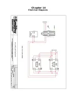
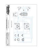
Страница 32: ...Chapter 14 Electrical Diagrams ...

Страница 33: ......

Отзывы: