background image

POSYC 4301/4302/4303 series industrial PCs

Installation, use and maintenance manual - EN 

Rev. 1.02

22 

6.5 Ethernet ports

There are two 10/100/1000 Mbps Ethernet ports that use standard RJ45 Ethernet connectors.

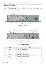
The two RJ45 connectors on the POSYC are shown below:

Each of the two Ethernet ports has two LEDs. The first, distinguished by the letter A, indicates the communi-

cation speed of the port involved. It is a two-color LED (green / orange); according to the speed at which the

Ethernet port is communicating, the LED takes on a different color. The second, yellow, marked by the letter

B, indicates the state of activity of the gate itself, or if the gate is connected or if it is communicating.

6.5.1   LED behavior of communication speed signaling

Below is a table that summarizes the possible speed states of Ethernet port:

6.5.2   LED behavior for signaling connection and communication activities

Name

State

Function

A

OFF

Ethernet port communicating at a speed of 10 Mbps

A

ON (Green LED)

Ethernet port communicating at a speed of 100 Mbps

A

ON (Orange LED)

Ethernet port communicating at a speed of 1 Gbps

Name

State

Function

B

OFF

Ethernet port not connected

B

BLINK OFF (Yellow LED)

Ethernet port connected and communicating

B

B

A

A

Port 1 (ETH1)

Port 2 (ETH2)

Содержание POSYC 4301

Страница 1: ...Italy www smitec it Installation use and maintenance manual INDUSTRIAL COMPUTERS POSYC 4301 4302 4303 BEFORE STARTING UP THE POSYC 430X SERIES INDUSTRIAL PCS CAREFULLY READ THIS MANUAL AND FOLLOW ALL...

Страница 2: ...rder codes 14 5 6 Accessories 15 6 Connections and LEDs 16 6 1 24V IN connector 18 6 2 RS485 serial port COM1 20 6 3 RS232 serial port COM2 21 6 4 Profibus card 21 6 5 Ethernet ports 22 6 5 1 LED beha...

Страница 3: ...ssed to the following professionals The present instructions must be made available to all the above individuals User User is a person a company or an institution that buys the equipment and uses it f...

Страница 4: ...n adopted DO NOT USE THE EQUIPMENT NOR MAKE ANY INTERVENTION BEFORE INTE GRALLY READING AND UNDERSTANDING THIS MANUAL IN PARTICULAR ADOPT ALL SAFETY PRECAUTIONS AND PRESCRIPTIONS INDICATED IN THIS MAN...

Страница 5: ...fety prescriptions aim at establishing a series of behaviors and obligations to be complied with while performing the activities described later on in this manual These prescriptions constitute the pr...

Страница 6: ...ta and the drawings in this manual might have been modified later always refer to the latest version All upgrades can be requested to SMITEC S p A directly Make sure that the personnel is qualified an...

Страница 7: ...andard devices Since it is sufficient to exert a slight pressure with a finger on its surface to make an immediate pointing this system is the main User Friendly feature of the POSYC computer In order...

Страница 8: ...POSYC 4301 4302 4303 series industrial PCs Installation use and maintenance manual EN Rev 1 02 8 POSYC 4303 with Emkey body...

Страница 9: ...e of writing of this document With the aim of improving or updating the product technologically SMITEC S p A reserves the right to change the technical features of the POSYC computer without notice Op...

Страница 10: ...eries industrial PCs Installation use and maintenance manual EN Rev 1 02 10 5 3 Mechanical characteristics 5 3 1 Mechanical dimensions 5 3 1 1 Front view Fixing 6 M5 threaded holes Weight 5 1 5 2 kg d...

Страница 11: ...POSYC 4301 4302 4303 series industrial PCs Installation use and maintenance manual EN Rev 1 02 11 5 3 1 2 Side view...

Страница 12: ...POSYC 4301 4302 4303 series industrial PCs Installation use and maintenance manual EN Rev 1 02 12 5 3 1 3 Rear view 5 3 1 4 Rear view recommended panel cut...

Страница 13: ...ased product are not guaranteed neither for production continuity nor for functionality Processor Intel Celeron N3160 Quad Core 1 6GHz 2 8GHz Burst Memory 4GB SODIMM DDR3L 1066MHz SDRAM CFast card 32G...

Страница 14: ...re POSYC 4301 with the following additions 5 4 1 3 Model POSYC 4303 Enclosed type UL Basic hardware POSYC 4301 with the following additions 5 5 Order codes Profibus interface card 1 on PCI EXPRESS bus...

Страница 15: ...0082 POSYC body with VESA fixing control panel body KZ010334 Push button panel EMKEY 4001 VAR 0 without body with white key black key illuminated blue key emergency key KZ010477 Push button panel EMKE...

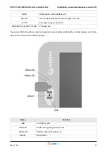
Страница 16: ...24V as shown in the following figures POSYC 4301 top panel view POSYC 4302 upper panel view Name Function COM1 RS485 serial communication port COM2 RS232 serial communication port DVI D Digital video...

Страница 17: ...opper and 2 sign aling LEDs as shown in the following figure HDMI HDMI audio video interface port 24V LED Green LED indicating 24V power supply presence 24V IN 24V power supply connection PROFIBUS onl...

Страница 18: ...ent 10A Stranded min 0 2mm Stranded max 1 5mm Insulating material PA Stranded with ferrule without plastic sleeve min 0 25mm Inflammability class according to UL 94 V0 Stranded with ferrule without pl...

Страница 19: ...mena Pay the utmost attention to prevent such phenomena complying with the provisions of the law in order to avoid damage to the device Utilisez un c ble de section appropri e dimensionn correctement...

Страница 20: ...rial PCs Installation use and maintenance manual EN Rev 1 02 20 6 2 RS485 serial port COM1 Below is the pinout of the DB9 male connector on the POSYC Serial RS485 COM1 Pin Signal 1 DATA 2 DATA 5 GND S...

Страница 21: ...is the pinout of the DB9 male connector on the POSYC 6 4 Profibus card Below is the pinout of the DB9 female connector on the POSYC Serial RS232 COM2 Pin Signal 1 DCD 2 RD 3 TD 4 DTR 5 GND 6 DSR 7 RTS...

Страница 22: ...different color The second yellow marked by the letter B indicates the state of activity of the gate itself or if the gate is connected or if it is communicating 6 5 1 LED behavior of communication sp...

Страница 23: ...al EN Rev 1 02 23 6 6 CFast card connector At the bottom of the POSYC is the connector for the CFast card The memory is secured inside the computer via a locking lever Bottom panel view Name Function...

Страница 24: ...hing the input output connectors on the computer panel directly unless you are equipped with suitable static electricity protection equipment any discharges on the con nectors could damage the applian...

Страница 25: ...rs supplied with the computer into the four holes at the corners of the frame A 6mm spanner wrench is required for tightening Slip the POSYC to the body by sliding the spacers in the appropriate seats...

Страница 26: ...the room temperature limits given in the specifications All this implies that within the panel that will surround the POSYC there must be suitable cooling systems to keep the temperature within the a...

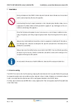
Страница 27: ...rs of twisted conductors are normally used to carry a given signal and its reference for example TD and GND the GND connection between the devices is essential for correct operation 7 4 2 RS485 serial...

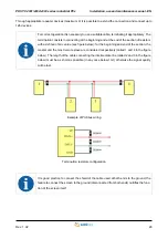
Страница 28: ...maximum transmission speed of the gate or 12 Mbps the length of the section is 100 meters For correct operation it is necessary to use a suitable cable terminating it appropriately The termination co...

Страница 29: ...g and at the end of the section of resistors with a defined ohmic value see figure below for the beginning and end of the section the master and the most remote slave are considered respectively calle...

Страница 30: ...g figures show the waveforms detected by means of an oscilloscope in different connection situa tions Example of a correct signal Example of a signal with unfinished lines Example of a signal with pla...

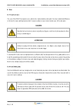
Страница 31: ...licking and right mouse button Refer to the software manual for further details 8 2 Front USB ports The front USB ports have been designed to connect temporary devices such as keyboards and flash disk...

Страница 32: ...ult POSYC searches for the operating system boot information in the mass memory used for the pre vious boot such as CFast and if it is found the boot device is not changed in contrast another is sough...

Страница 33: ...POSYC via USB flash disk for activities that need access to the CFast for example backup or restore to POSYC off extract the CFast from its housing insert the USB flash disk containing the operating s...

Страница 34: ...battery The replacement of the internal clock battery in addition to ensuring the maintenance of the same is useful not to lose the settings of the CMOS Setup basic information for the operation of th...

Страница 35: ...POSYC 4301 4302 4303 series industrial PCs Installation use and maintenance manual EN Rev 1 02 35 BATTERY Battery position...

Страница 36: ...stored in the BIOS to guarantee operation In the event that there is a loss of memory of the CMOS Setup for example after the backup battery has been used up these will automatically reset when the PO...

Страница 37: ...HDMI 7 17 HMI 7 I Installation 24 IP65 7 M Main power supply voltage 9 Maximum altitude 9 Memory 7 13 Monitor 13 O Operating temperature 9 P Panel mounting 24 Precautions 6 Processor 7 13 Profibus 17...

Отзывы: