background image

IR lamp control module - HELCON 11XX series -

Installation, use and maintenance manual - EN 

Ver. 1.02

4  Technical data

4.1 Environmental characteristics

All the technical information reported in this section are consistent with the hardware con-

figuration of the HELCON module produced at the date of writing of this document. With the

aim of technologically improving or updating the product, SMITEC S.p.A. reserves the right

to change the technical characteristics of the HELCON module without prior notice.

Operating temperature

Model: HELCON 1110

Code: KZ010605

0°C ÷ +45°C

Operating temperature

Model: HELCON 1108

Code: KZ010604

0°C ÷ +50°C

Storage temperature

-20°C ÷ +70°C

Maximum altitude

1000 m a.s.l. at nominal output current

2000 m a.s.l. with current derating

Output current derating as a function of 

altitude

Degree of protection of the enclosure

IP65

Содержание HELCON 10 Series

Страница 1: ...ec it Installation use and maintenance manual CONTROL MODULE IR LAMPS HELCON 11XX SERIES BEFORE USING THE MODULES OF THE HELCON 11XX SERIES YOU MUST READ THIS INSTALLATION AND USE MANUAL CAREFULLY AND...

Страница 2: ...ommissioning 12 5 1 Preliminary operations 12 5 2 Mechanical assembly 13 5 2 1 Positioning and fixing 13 5 3 Connections 16 5 3 1 Power supply J1 17 5 3 1 1 Connection scheme 18 5 3 1 2 Electromagneti...

Страница 3: ...y even with power supply with distorted sinusoidal voltage To obtain this functional improvement of the device the SSR modules of the HELCON 10XX series and of the HELCON 11XX series are not interchan...

Страница 4: ...AKE ANY INTERVENTION BEFORE INTE GRALLY READING AND UNDERSTANDING THIS MANUAL IN PARTICULAR ADOPT ALL SAFETY PRECAUTIONS AND PRESCRIPTIONS INDICATED IN THIS MANUAL THE EQUIPMENT MUST BE USED FOR PURPO...

Страница 5: ...ming the activities described later on in this manual These prescriptions constitute the prescribed method of operating the device in a way that is safe for person nel equipments and environment The s...

Страница 6: ...this manual might have been modified later always refer to the latest version All upgrades can be requested to SMITEC S p A directly Make sure that the personnel is qualified and adequately informed...

Страница 7: ...ecurely to the protective conductor PE using the appropriate terminals to avoid risk of electrolocution Never use the device partially or totally disassembled Danger of electric shock and or damage to...

Страница 8: ...With the aim of technologically improving or updating the product SMITEC S p A reserves the right to change the technical characteristics of the HELCON module without prior notice Operating temperatur...

Страница 9: ...010604 60 0A Power input main power Model HELCON 1110 Code KZ010605 25 5kW Power input main power Model HELCON 1108 Code KZ010604 24 0kW Auxiliary power supply voltage 24V DC 15 20 Current consumption...

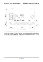
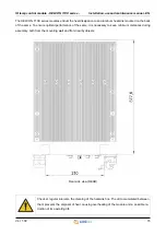
Страница 10: ...n use and maintenance manual EN Ver 1 02 10 4 3 Mechanical specifications 4 3 1 Weight The following table shows the weight of the various models 4 3 2 Dimensions External measurements of the only dev...

Страница 11: ...24kW total KZ010605 HELCON 1110 IR 400V single phase lamps control module with 10ch x 3kW max 25 5kW total Order code Article EE500170 Spare fuse class gG 12A 500V RAPID 10 3x38 mm EE500232 Spare fuse...

Страница 12: ...directly touching the input output connectors located on the underside of the HEL CON module unless you are equipped with suitable protective equipment for static electric ity any discharges on the c...

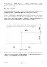
Страница 13: ...thread M6 MA pitch The stem portion of the screw entering the insert must not exceed 14 mm recommended value 12 mm Use screws with a strength class of 8 8 or higher the recommended tightening torque i...

Страница 14: ...considerable vibration which could damage the device In this case it is recommended to use dampers silentblock made of elastomeric material whose characteris tics must be determined on the basis of th...

Страница 15: ...back of the same To ensure optimal performance of the same it is necessary to keep minimum distances during assembly both from the mounting wall and from nearby objects Check at regular intervals the...

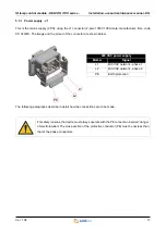
Страница 16: ...1 02 16 5 3 Connections The connectors are located at the bottom The following image shows the connections available on the bottom of the equipment J3 J1 J4 J5 J2 Connections Marker Description J1 Ma...

Страница 17: ...pinout of the connector are shown below The following paragraphs describe in detail how the connections are to be made For safety reasons the device must always operate with the PE connection inserted...

Страница 18: ...f the magnetothermic type with tripping curve C complying with the EN IEC 60947 1 standard The size of the same must be 63A for modules with 8 outputs and 80A for those with 10 outputs The short circu...

Страница 19: ...above protection devices are used upstream of them This table presupposes a laying of the cable in free air similar to the installation category E of IEC 60364 5 52 If you intend to use cables of dif...

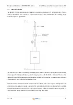
Страница 20: ...tives In order to avoid interference and or malfunctions of the module and other equipment it is advisable to ensure that the power cables are placed at a safe distance from other cables belonging to...

Страница 21: ...To facilitate this termination the resistor is integrated into the KF131326 connector to be connected to the J4 connector The termination at the beginning of the line is usually integrated into the ma...

Страница 22: ...n the limits of the HELCON 11XX series modules refer to the specific paragraph If these voltages are outside the prescribed limits the unit may be damaged Check the polarity of the voltages before con...

Страница 23: ...er Phoenix Contact code 1436564 makes the output of the external 24V DC power supply available The pinout of the connector is shown in the following image The 24VDC output supplied by the J5 connector...

Страница 24: ...form the user about the sta tus of the field bus FLxIO the power supply line and the operating condition 5 4 1 Fieldbus status LEDs have the following meaning in compliance with the FLxIO standard the...

Страница 25: ...communication prob lems and could lead to uncontrolled system behavior It is possible to address up to 15 devices in the same bus The addressing of the HELCON 11XX series modules can be done in two d...

Страница 26: ...is necessary to remove the pro tective cap of the same by unscrewing it anticlockwise with the aid of a suitable sized slotted screwdriver The switch can be set to 16 different positions from 0 to F...

Страница 27: ...its operation follows In this mode the module address is set automatically according to the order of connection of the device in the bus In fact taking advantage of the cascade connection of the bus t...

Страница 28: ...ous versions of the mod ule 5 6 1 HELCON 1108 Connector female fruit 16 pole 500V 16A with spring connection made of self extinguishing thermoplastic resin code N120770 manufacturer Weidmuller Functio...

Страница 29: ...with spring connection made of self extinguishing thermoplastic resin code CSHF 24 manufacturer Ilme Function Pinout Lamp 1 PIN 1 PIN 13 Lamp 2 PIN 2 PIN 14 Lamp 3 PIN 3 PIN 15 Lamp 4 PIN 4 PIN 16 La...

Страница 30: ...ement electronics also allows the following features Compensation of the mains voltage the output power output is made independent of the supply voltage Diagnostic check of the lamps Reading of the re...

Страница 31: ...the Helcon module can be parametrized by the process controller to de lay the ignition command of the TRIACs with respect to Zero Crossing and therefore ignite them when the half wave voltage is high...

Страница 32: ...IR lamp control module HELCON 11XX series Installation use and maintenance manual EN Ver 1 02 32...

Страница 33: ...e and its components can be stored in their original packaging and always in a covered place even if they are packed Protect the device against dust and atmospheric agents Do not stack more than 3 mod...

Страница 34: ...can be carried out through FLxIO field bus remote programming if the master device recog nizes that the module is programmed with a different FW version as compared to the version loaded in the memor...

Страница 35: ...HELCON module it will be necessary to open the door of the device using the special dedicated key Insert the key in the seat shown in the figure and turn it anticlockwise The door opens with a book o...

Страница 36: ...ly Open the door with the appropriate key provided Open the failed fuse holder door Remove the faulty fuse Insert the replacement fuse Use only fuses with the same rated current and the same type as t...

Страница 37: ...the appropriate seat of the terminal board and extract the cable Mark the cables to avoid inverting them during wiring Unscrew the two fixing screws of the defective SSR module using a 4 mm hexagonal...

Страница 38: ...ect the connection cables in reverse order of disassembly Reposition the plexiglass protection and fix it with the appropriate screws tighten the screws with a torque tool to a torque of 0 5 Nm 10 Clo...

Страница 39: ...eries Installation use and maintenance manual EN Ver 1 02 39 Before tightening all the terminals of the fuse holders always make sure to remove power supply from the device Failure to perform maintena...

Страница 40: ...vice must be carried out according to the laws in force in the country where it was in stalled Should the disposal be partial frame heat sink electronic boards separate the components made of plastic...

Страница 41: ...Disposal 40 E Electrocution 7 Electromagnetic compatibility 20 F Fieldbus 20 24 Firmware upgrade 34 Fixing 13 FLxIO 20 30 Fuse holder door 36 H Handling 6 Hot parts 7 I Ignition 31 Installation 12 IP...

Отзывы: