background image

HRX-OM-R016 

Chapter  5      Display  and  setting  of  various  functions 


HRS Series 

5.7

 Run timer, stop timer function 


5-15 

5.7  Run timer, stop timer function 

5.7.1 

Run timer and stop timer function 

This function starts or stops operation automatically when a set time has 
passed. 

The time can be set according to the customer’s working hours. Set 

the circulating fluid temperature in advance. 

[Run timer] is a function to start operation after a set time. Stop timer] is a 
function to stop operation after a set time. It is possible to set both [Run 
timer] and [Stop timer]. The set time of both the [Run timer] and [Stop timer]


can be up to 99.5 hours, in 0.5 hour units. 


When communication is used


If  the  communication  mode  is  DIO  REMOTE,  SERIAL  mode,  this  function 
does  not  operate.  DIO  REMOTE,  SERIAL  mode  operation/stop  signal  has 
priority. 


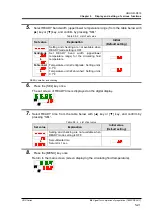
●Run timer 

Run timer] starts operation after the set time. 

If the thermo-chiller is already operating or the pump is operating 
independently, this function does not operate even if the set time has 
passed. 

Operation can start when the condition is normal and there is no alarm 
generated. 

The [

] lamp lights up when the run timer is set. The [

] lamp is turned 

off when the operation is started by the run timer. 

The [

] lamp is not turned off if the Stop timer is set. 

The Run timer setting is reset when the main power supply is cut or a 

power failure occurs. Please reset. 


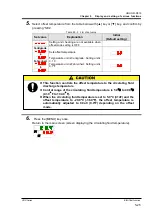
●Stop timer 

The [

] lamp lights when the Stop timer is set. The [

] lamp is turned 

off if the operation is stopped by the Stop timer. 

The [

] lamp is not turned off if the Run timer is set. 

The Stop timer setting is reset when the main power supply is cut or a 

power failure occurs. Please reset. 


Содержание HRS030-A-20 series

Страница 1: ...7 Operation Manual Installation Operation Original Instructions Thermo chiller Air Cooled refrigerated type Water Cooled refrigerated type HRS030 A 20 HRS030 W 20 Keep this manual available whenever necessary 2017 SMC CORPORATION All Rights Reserved ...

Страница 2: ...tion and operation of the product Only people who understand the basic operation of the product through this manual or who perform installation and operation of or have basic knowledge about industrial machines are allowed to work on the product This manual and other documents attached to the product do not constitute a contract and will not affect any existing agreements or commitments It is stri...

Страница 3: ...terial Safety Data Sheet MSDS 1 8 Chapter 2 Name and Function of Parts 2 1 2 1 Part number of product 2 1 2 2 Name and Function of Parts 2 2 2 3 Function of Parts 2 3 2 4 Operation display panel 2 4 Chapter 3 Transport and Setting Up 3 1 3 1 Transport 3 1 3 1 1 Transportation using casters 3 2 3 2 Installation 3 3 3 2 1 Environment 3 4 3 2 2 Location Required ventilation rate and facility water so...

Страница 4: ...of various functions 5 1 5 1 List of function 5 1 5 2 Function 5 2 5 2 1 Key operations 5 2 5 2 2 List of parameters 5 4 5 3 Main screen 5 7 5 3 1 Main screen 5 7 5 3 2 Display on the main screen 5 7 5 4 Alarm display menu 5 8 5 4 1 Alarm display menu 5 8 5 4 2 Content of display of alarm display menu 5 8 5 5 Inspection monitor menu 5 9 5 5 1 Inspection monitor menu 5 9 5 5 2 Checking of the Inspe...

Страница 5: ...ching setting and checking 5 32 5 15 Alarm buzzer sound setting 5 33 5 15 1 Alarm buzzer sound setting 5 33 5 15 2 Alarm buzzer sound setting and checking 5 33 5 16 Alarm customize function 5 34 5 16 1 Alarm customize function 5 34 5 16 2 Alarm customize function setting and checking 5 36 5 16 3 Setting of temperature alarm monitoring method and alarm generation timing 5 48 5 17 Data reset functio...

Страница 6: ...g 8 1 8 1 Control of Circulating Fluid Quality 8 1 8 2 Inspection and Cleaning 8 2 8 2 1 Daily check 8 2 8 2 2 Monthly check 8 3 8 2 3 Inspection every 3 months 8 4 8 2 4 Inspection every 6 months 8 5 8 2 5 Inspection for winter season 8 6 8 3 Consumables 8 6 8 4 Stop for a Long Time 8 7 8 4 1 Discharge of the circulating fluid and facility water 8 7 Chapter 9 Documents 9 1 9 1 Specifications List...

Страница 7: ... R016 Contents HRS Series 9 6 3 HRS030 20 MT 9 8 9 7 Required facility water flow for water cooled type 9 8 9 8 Compliance 9 9 9 9 Sample DoC 9 10 9 10 Daily Check Sheet 9 11 Chapter 10 Product Warranty 10 1 ...

Страница 8: ...HRX OM R016 Contents HRS Series ...

Страница 9: ...uld read and understand the safety related information in this manual carefully before starting work The safety manager is responsible for strictly observing safety standards but responsibility in respect to safety standards during daily work resides with each individual operator and maintainance personnel Do not use the materials that rust or corrode for the circulating fluid and facility water c...

Страница 10: ...ing to severity DANGER WARNING CAUTION 1 3 2 Definition of Serious injury and Minor injury Serious injury This term describes injuries that result in after effects including loss of eyesight burns electrical shock fracture poisoning etc and requires long term treatment or hospitalization Minor injury This term describes injuries that do not need long term treatment or hospitalization Others exclud...

Страница 11: ...side this product unless you have been trained to do so DO NOT work inside this product unless you have been trained to do so DO NOT work inside this product unless you have been trained to do so DO NOT work inside this product unless you have been trained to do so DO NOT work inside this product unless you have been trained to do so DO NOT work inside this product unless you have been trained to ...

Страница 12: ...ctions 1 3 Hazards HRS Series 1 4 1 3 4 Locations of Hazard Labels There are various warning labels on the product to show the potential hazards Fig 1 1 Warning label position For air cooled type Fig 1 2 Warning label position Rear Front ...

Страница 13: ...betical order 1 O Repeated from O to Z in alphabetical order with O for January and Z for December 2014 S 2 P 2015 T 3 Q Fig 1 3 Position of product label 1 5 Safety Measures 1 5 1 Safety Instructions for Use Read and understand this manual carefully before using the product Before starting maintenance of the product be sure to lock out and tag out the breaker of the user s power supply If operati...

Страница 14: ...ent for each work Transport Installing and Uninstalling Handling of circulating fluid Operation Always use safety shoes gloves and head protection when transporting installing or uninstalling the product Always use safety shoes gloves mask apron and eye protection when handling the circulating fluid Always use safety shoes and gloves when operating the product ...

Страница 15: ...he power supply switch at the back of the product to stop the operation of the thermo chiller Fig 1 4 Location of the switch for the power supply 2 Be sure to shut off the breaker of the facility power supply the power supply of the user s machine Fig 1 5 Shut off of facility power supply Even when the power supply swich is turned off some of the internal circuits are still energized unless the us...

Страница 16: ...cal laws and regulations 1 8 Material Safety Data Sheet MSDS If the material safety data sheets of chemicals used in this product are needed contact an SMC s sales distributor Any chemicals used by the user must be accompanied by an MSDS Comply with the laws and regulations in each country for the disposal of refrigerant and compressor oil The release of refrigerant in to the atmosphere is banned ...

Страница 17: ...duct Label and check the part number of the product Fig 2 1 Part number of product 20 A 030 030 HRS Cooling capacity Cooling method Piping thread type Power supply Null F N Rc G PT G conversion fitting is included NPT PT NPTconversion fitting is included A Air cooled refrigerator type W Water cooled refrigerator type 20 1 phase AC200 230V 50 60Hz 2600W 3200W 50 60Hz Option Null None J Automatic wa...

Страница 18: ...d level gauge Ventilation air inlet Dustproof filter Lid for circulating fluid fill port Operation display panel 660 mm 26 in 35 mm 1 4 in 500 mm 19 7 in 21 mm 0 8 in Power switch Power cable hole Drain port With plug Circulating fluid return port Rc1 2 Circulating fluid outlet port Rc1 2 Model no label Facility water outlet Rc3 8 For water cooled type Optuon B Earth leakage breaker Drain port Rc1...

Страница 19: ... returns to the return port Drain port This drain port to drain the circulating fluid out of the tank The plug is connected to standard pump type at the time of shipment The ball valve is installed in the high pump head type Facility water inlet For water cooled type A facility water inlet to which the facility water is fed through piping The pressure of facility water should be in a range of 0 3 ...

Страница 20: ...ped Flashes during stand by for stop Interval 0 5 seconds Flashes during independent operation of the pump Interval 0 3 seconds Flashes during anti freezing function At standby Interval 2 seconds At operation Interval 0 3 seconds 4 4 ALARM lamp Flashes with buzzer when alarm occurs Interval 0 3 seconds 5 4 lamp Lights up when the tank level indicator falls below the LOW level 4 3 lamp Lights up wh...

Страница 21: ...o follow these instructions for transport Only persons who have sufficient knowledge and experience about the product and system are allowed to transport and set up the product Especially pay attention to personal safety Never lay the product on its side The compressor oil will leak in to the refrigerant piping which may cause early failure of the compressor Drain the residual fluid from the pipin...

Страница 22: ...destination Do not hold the product by the cap to move it This will apply excess force to the piping of internal parts which may lead to malfunctions such as fluid leakage 3 To push the front or rear panel push it by the corner Pushing by the center of the panel may deform the shape Care should be taken Fig 3 1 Transportation using casters Handle Unlocking Press Corners This product is heavy Care ...

Страница 23: ...of the product or injure the operator Keep the ambient temperature of the product between 5 to 40o C Operation below 5o C may cause the compressor failure and operation above 40o C may cause the product to overheat and shut down Do not set up the product in places possibly exposed to leakage of flammable gas Should any flammable gas stay around the product the product may cause a fire Do not use t...

Страница 24: ...e gas organic solvent chemical solution or flammable gas the product is not flame proof Location where the ambient temperature is out of the following range In transportation and In storage 0 to 50 C with no water or circulating fluid in piping In operation 5 to 40 C Location where the ambient humidity is out of the following range or where condensation occurs In transportation and storage 15 to 8...

Страница 25: ...s 1 Max ambient temp Use the product in lower ambient temperature than the described value at each altitude 2 Cooling capacity coefficient The product s cooling capacity will lower to one that multiplied by the described value at each altitude Bevelled place Location where the product is affected by strong vibrations or impacts Condition that applies external force or weight causing the product to...

Страница 26: ...al temp of 3 o C between inside and outside of installation area Differential temp of 6 o C between inside and outside of installation area HRS030 A 20 Approx 6 100 60 Facility water source to be prepared For water cooled type Table 3 2 Facility water source to be prepared Model Heat Radiated kW Facility water temp range o C Required facility water rate l min Facility water temprature 25o C 32o C ...

Страница 27: ...enance move the thermo chiller into a space where maintenance work is possible Fig 3 2 Installation space 100mm or more 100mmor more 500mm or more 300mm or more 100mm or more The temperature of the outlet of for the ventilation of the thermo chiller and the panel surface may become approx 50o C or higher When placing the thermo chiller ensure the thermo chiller does not affect surrounding environm...

Страница 28: ...tallation area 2 After moving lock the front casters again Fig 3 3 Installation procedures Fixture Follow the procedure below when fixing the thermo chiller to the floor or the mounting frame 1 Prepare the fixing bracket shown below Not included in the package Item Part number Anti seismic brackets HRS TK001 2 Use M8 foundation bolts to fix the product within the dimensions below Fig 3 4 Anti seis...

Страница 29: ...he user s power supply Wiring with the product energized is strictly prohibitted The wiring must be conducted using cables complying with Table 3 3 firmly and secured to the product to prevent the external force of cables being applied to the terminals Incomplete wiring or improper securing of wiring may cause electrical shock excessive heat and fire Ensure a stable power supply with no voltage su...

Страница 30: ...L L E N Earth leakage breaker Secondary side Crimp terminal 3pcs Terminal screw is M3 5 Prepare the crimp terminal which is suitable for the cable diameter Plug Prepared by customer L E N The electrical facilities should be installed and wired in accordance with local laws and regulations of each country and by a person who has knowledge and experience Check the power supply Operation with voltage...

Страница 31: ...nnect the power supply cable to the secondary side of the earth leakage breaker and grounding 2 Plug the power supply cable in to the power cable connector on the product Fig 3 6 Wiring of power supply L N E Earth Power cable hole Earth leakage breaker E Grounded socket Power supply connector ...

Страница 32: ... capacity 35mA or more min load current 5mA and cable dia 0 14 to 1 5mm2 2 Connect the remote control cable and the switch to the connector for the contact input output supplied as an accessory Then mount the ferrite core 3 turn supplied as an accessory See below This is an example of wiring Refer to the Operation Manual for communication for details Fig 3 7 Wiring of contact for remote signal inp...

Страница 33: ... Transport and Setting Up HRS Series 3 3 Installation 3 13 3 Plug the prepared connector in to the contact input output connector that is on the back of the thermo chiller Fig 3 8 Connecting the Remote control signal cable ...

Страница 34: ...ote Contact closed At non remote Contact open With power supply shut off Contact open Output current 3 Terminal no 1 2 Alarm signal B At generation Contact open Not generated Contact closed With power supply shut off Contact open Tips This product has three output signals which can be customized depending on the customer s application Signals below can be output Refer to the Communications Operati...

Страница 35: ... procedure below for connecting multiple thermo chillers Configuration of connection One host computer One thermo chiller or one host computer N thermo chillers Max 31 thermo chillers can be connected Fig 3 9 Connection of RS 485 Tips Both ends of the communication connection the end nodes need to be connected to the host computer The terminal resistance of this product can be set by the operation...

Страница 36: ...ading of alarm condition can be done by remote control Refer to the Communications Operation Manual for more details Wiring of communication cable Be sure to wire as shown in the figure below Configuration 1 master 1 thermo chiller Fig 3 10 Connection of RS 232C 2 3 5 R D S D S G 2 3 5 R D S D S G Master This product Be sure to shut off the breaker of the facility power supply the user s machine p...

Страница 37: ...uring connection of piping When the thermo chiller is water cooled refrigerated type the temperature of the outlet of the facility water may become approx 60o C depending on operating conditions Hold the piping port firmly with specific wrench when tightening The piping should be selected with due consideraton of pressure and temperature Otherwise the piping can burst in service Do not use the mat...

Страница 38: ...lter Rc1 2 20μm HRS PF003 3 Flow meter 0 to 50L min 4 Pressure gauge 0 to 1 0MPa 5 Others pipe hose etc ø15 or more Y strainer Rc1 2 1000 Filter Rc1 2 20μm Note FQ1011N 04 T020 B X61 Note The filter shown above cannot be directly connected to the thermo chiller Install it in the user s piping system 2 Install either the strainer or filter If foreign objects with a size of 20 μm or more are likely ...

Страница 39: ... separately To control the concentration of the ethylene glycol aqueous solution a concentration meter is available separately from SMC Item No Remarks Ethylene glycol aqueous solution 60 HRZ BR001 Please dilute to 15 with tap water and use it Densitometer HRZ BR002 Tank lid Circulating fluid fill Liquid level Check the drain port is plugged or closed by the valve to prevent the supplied circulati...

Страница 40: ...Port size Piping specifications Automatic water fill inlet Rc3 8 Supply pressure 0 2 to 0 5MPa Overflow outlet Rc3 4 Piping should be within f19 of I D and 5m of length Riser piping trapping area should be avoided Fig 3 14 Piping to automatic fluid filling port and overflow port Supplying fluid from the automatic fluid filling port Fluid filling starts if the power supply switch is turned ON when ...

Страница 41: ...ill be cut to protect the product and the alarm AL21 DC line fuse cut will be generated Refer to Chapter 6 for handling of alarms One external switch can be connected to contact input signal 1 and one to contact input signal 2 Two in total The external switch cannot be connected to the contact input signal 1 depending on the communication mode Table 3 7 shows the setting Table 3 7 Sets external sw...

Страница 42: ...elay timer for reading By setting this timer the external switch monitoring starts after the time set by the delay time of reading since the operation start 0 is the default setting Set a time which is suitable for your environment Example When using a flow switch When operation is started it takes time for the fluid to reach the piping and the flow switch to detect the flow Set the time for the f...

Страница 43: ...Depending on the external switch output type wire the switch to the communication connector for contact input output which is included as an accessory as shown below Mount the ferrite core 3 turns which is included as an accessory This is an example of wiringRefer to the Communications Operation Manual for more details NPN open collector output Fig 3 16 Wiring of the external switch NPN open colle...

Страница 44: ...external switch Displa y Item Initial value Default setting Example Reference page Category Communication mode LOC LOC 5 19 Communication setting menu Contact input output communication Contact input signal 1 RUN SW_A Contact input signal 1 type ALT ALT Contact input signal 1 delay timer time delay of reading 0 0 Contact input signal 1 OFF detection timer 0 2 Contact input signal 2 OFF OFF Contact...

Страница 45: ...n operation Check that the facility water circuit is not shut off by valves Tips The product is equipped with a water regulator which does not allow the facility water to flow unless the product is started Automatic fluid filling piping When option J With automatic fluid filling is selected Confirm that the automatic fluid filling port piping is connected properly Over flow port piping When option...

Страница 46: ...y changes to the main screen which displays the circulating fluid outlet temperature The set value of circulating fluid temperature is displayed as SV on the panel The present value of circulating fluid temperature is displayed as PV on the panel Fig 4 1 Power supply 4 2 2 Setting of circulating fluid temperature Press the and buttons on the operational panel to change the SV to required value Whe...

Страница 47: ...ndently while the PUMP key is pressed The RUN lamp green flashes while the pump is operating independently and the circulating fluid in the tank is supplied to the customer s device and piping This can be done to check for leakage and to discharge air from the piping If the fluid level in the tank reaches the lower limit a buzzer will sound and alarm no AL01 tank fluid level is low is displayed on...

Страница 48: ...luid up to the H mark on the tank Fig 4 6 Filling of Circulating Fluid Flash Press together Tank lid Filling of Circulating Fluid Liquid level ON Be sure to reset the alarm on the operation display panel of the alarm Alarm reset is not accepted from any screen except the alarm display menu Refer to 5 2 1 Key operations Supply the circulating fluid up to the H mark on the tank Operation will stop w...

Страница 49: ... fluid temp Circulating fluid set temp Press the PUMP key press RUN STOP key and MENU key simultaneously to start independent operation of the pump Fig 4 7 Alarm release 5 Repeat steps 1 to 4 to supply the circulating fluid to the customer s device and piping The tank level must be H on the tank liquid level indicator Press together OFF OFF Be sure to reset the alarm on the operation display panel...

Страница 50: ...s on refer to Chapter 7 Alarm indication and trouble shooting 1 Press the RUN STOP key on the operation panel The RUN lamp lights up in green and the product starts running The circulating discharge temperature PV is controlled to the set temperature SV Fig 4 8 Starting the product ON Press When an alarm occurs Refer to Chapter 7 Alarm indication and trouble shooting Allow at least five minutes be...

Страница 51: ...peration panel flashes green at 1 second intervals and continues operation to prepare to stop After approx 15 seconds the RUN lamp goes off and the product stops Fig 4 9 Stopping the product 2 Turn off the power supply switch All LEDs go off Flash OFF 等 Press Be sure to shut off the breaker of the facility power supply the user s machine power supply before wiring Also drain the circulating fluid ...

Страница 52: ...ed range The tank level is within the specified range 4 6 Adjustment of Circulating Fluid Flow adjustment If the flow rate is less than 7L min it will not be able to achieve the specified cooling capacity The adjustment of flow rate should be performed using a manual bypass valve and monitoring the pressure or flow rate in the customer s device referring to the recommended piping flow shown in Fig...

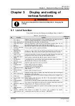
Страница 53: ...r the power supply is turned on 5 10 9 Anti freezing function Circulating fluid is protected from freezing during winter time or night time Set beforehand if there is a risk of freezing 5 11 10 Key click sound setting Operation panel key sound can be set on off 5 12 11 Changing temp unit Temperature unit can be changed Centigrade o C Fahrenheit o F 5 13 12 Changing pressure unit Pressure unit can ...

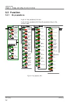
Страница 54: ...SV PV SV Key lock Run timer Setting menu Stop timer READY mode READY band width READY time Offset mode Offset temperature Recover from power failure Anti freezing PV SV PV SV PV SV PV SV PV SV PV SV PV SV PV SV PV SV PV SV Data reset Pump accumulated operating time reset Fun motor accumulated operating time reset Compressor accumulated operating time reset Key click sound Temperature unit Pressure...

Страница 55: ... Communicati on mode Serial protocol Communication specifications RS 485 terminal Slave address MODBUS Communicati on speed MODBUS Slave address Simple communicatio n protocol Communication speed Simple communication protocol Response delay time Simple communication protocol Communicati on range Simple communicati on protocol BCC Simple communicatio n protocol Data length Simple communicati on pro...

Страница 56: ...culating fluid outlet pressure Pressure of higher pressure refrigerant circuit Pressure of lower pressure refrigerant circuit Electric resistivity Accumulated operation time of the pump Accumulated operation time of the fun motor Accumulated operation time of the compressor Accumulated operation time Key lock OFF 5 6 Setting menu Run timer 0 0H 5 7 Stop timer 0 0H READY mode OFF 5 8 READY band wid...

Страница 57: ...ion pressure for circulating fluid discharge pressure drop 0 05MPa 7PSI Changing of communication error OFF The monitoring time of communication error 30 sec Unused Changing of Contact input signal 2 detection A STP Changing of DC line fuse cut A STP Changing of water leakage A STP Changing of upper limit of electric resistivity conductivity A RUN Upper limit of electric resistivity conductivity C...

Страница 58: ...T Unused Unused Contact input signal 2 OFF Contact input signal 2 type ALT Contact input signal 2 delay timer time delay of reading 0 Contact input signal 2 OFF detection timer 0 Contact output 1 function RUN Contact output 1 operation A Selected for contact output 1 AL 01 Contact output 2 function RMT Contact output 2 operation A Selected for contact output 2 AL 01 Contact output 3 function ALM C...

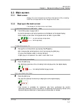
Страница 59: ... set temperature by pressing the key After changing the set temperature set it by pressing the SEL key The set value flashes while it is being changed If SEL key is not pressed the value is reset after 3 sec Circulating fluid discharge pressure Diaplay 3 Press the SEL key The discharge pressure of the circulating fluid is displayed on the digital display Electric resistivity conductivity Display 4...

Страница 60: ...s 5 4 2 Content of display of alarm display menu The alarm display screen appears when an alarm is gernerated When multiple alarms are generated the latest alarm is displayed on the screen Each time the SEL key is pressed the alarms are displayed in order starting from the latest one The main screen is displayed when the alarm is reset The main screen is displayed when MENU key is pressed while an...

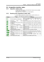
Страница 61: ...perature of the circulating fluid return Temperature of the inlet of the compressor Displays the temperature of the inlet of the compressor Circulating fluid outlet pressure Displays the circulating fluid outlet pressure at the outlet Pressure of higher pressure refrigerant circuit Displays the pressure of higher pressure side of the refrigerant circuit Pressure of lower pressure refrigerant circu...

Страница 62: ...Press the SEL key once The temperature of the circulating fluid return is displayed on the digital display Displays the temperature of the circulating fluid returning from the customer s device Check of the temperature of the inlet of the compressor 3 Press the SEL key once The temperature of the refrigerant circuit compressor inlet is displayed on the digital display Displays the temperature of t...

Страница 63: ...electric resistivity conductivity is displayed on the digital display This function is available for customers who have purchased the electric resistivity conductivity sensor set which is a separately sold accessory Refer to the Operation Manual attached to these optional accessories for details Check of the accumulated operation time of the pump 8 Press the SEL key once The accumulated operation ...

Страница 64: ... the fan motor The accumulated time of the digital display shows Also AL29 fan motor maintenance alarm is not generated Check of the accumulated operation time of the compressor 10 Press the SEL key once The accumulated operation time of the compressor is displayed on the digital display Displays the accumulated operation time of the compressor Refer to Table 5 5 2 for the display AL30 Compressor ...

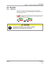
Страница 65: ...nged by operator error Operation can be started stopped by the RUN STOP key even while key lock is set If you try to change the set value with and key while key lock is set is displayed for 1 sec on the screen The set value cannot be changed Refer to the figure below PV SV PV SV During key lock setting no other setting is available Release the key lock setting for other setting ...

Страница 66: ... available OFF 1 Press and hold the MENU key for approx 2 sec Repeat pressing until the setting display for key lock setting appears on the digital display Key lock setting and checking 2 Select ON from the table below with key or key and confirm with SEL Table 5 6 2 List of set value Set value Explanation Initial value Default setting Key lock function OFF Key lock function ON 3 Press the MENU ke...

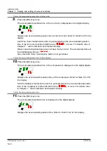
Страница 67: ...e this function does not operate DIO REMOTE SERIAL mode operation stop signal has priority Run timer Run timer starts operation after the set time If the thermo chiller is already operating or the pump is operating independently this function does not operate even if the set time has passed Operation can start when the condition is normal and there is no alarm generated The lamp lights up when the...

Страница 68: ...op after 5 5 hours Now 1H 2H 3H 4H 5H 6H 7H 8H Stopped Operating Stopped Operating Stopped Run timer Stop timer Set to stop after 2 hours Set to start after 5 5hours Now 1H 2H 3H 4H 5H 6H 7H 8H Operating Stopped Operating Stopped Operating Set while the power supply switch is ON while the power is supplied The setting is released when operation is started or stopped by the timer Resetting is neces...

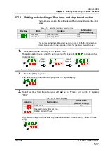
Страница 69: ...se refer to the applicable items for the timer you wish to use 1 Press and hold the MENU key for approx 2 sec Repeat pressing the key until the setting screen for key lock appears on the digital display Run timer Setting and checking 2 Press the SEL key once The set screen of run timer is displayed on the digital display 3 Select run timer from the table below with key or key and confirm by pressi...

Страница 70: ... set value Set value Explanation Initial value Default setting Timer OFF to Operation stops after set time Setting unit is 0 5 hour E g Set at 4 30pm Operation stops 1 hour and 30 minutes later at 6 00pm 6 Press the MENU key once Return to the screen displaying the circulating fluid temperature 7 Once the run timer is set leave the power supply to the product on The product will start automaticall...

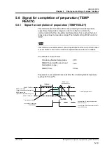
Страница 71: ...n is available when contact input output and serial communication is used Refer to the Communications Operation Manual for more details An example is shown below Circulating fluid set temperature 20 READY band width upper lower temperature range 2 READY time 60 sec Preparation is completed 60 seconds after the circulating fluid temperature reaches 18 o C to 22 o C Circulating set fluid 20 READY TE...

Страница 72: ... time Sets time of signal for completion of preparation 10 sec 1 Press and hold the MENU key for approx 2 sec Repeat pressing the key until the setting screen for key lock appears on the digital display READY mode Setting and checking 2 Press the SEL key 3 times The set screen of ready mode is displayed on the digital display 3 Select ON from the table below with key or key and confirm by pressing...

Страница 73: ...the circulating fluid temperature Temperature unit is Centigrade Setting unit is 0 1 o C Temperature unit is Fahrenheit Setting unit is 0 1 o F Fahrenheit to READY time Set and checking 6 Press the SEL key once The set screen of READY time is displayed on the digital display 7 Select READY time from the table below with key or key and confirm by pressing SEL Table 5 8 4 List of set value Set value...

Страница 74: ...g sending of the fluid MODE Explanation MODE1 Control the temperature so that the discharge temperature of the circulating fluid is circulating fluid set temperature offset temperature Circulating fluid temperature indicates the circulating fluid discharge temperature MODE2 Control the temperature so that the discharge temperature of the circulating fluid is circulating fluid set temperature Circu...

Страница 75: ...circulating fluid set temperature offset temperature Even if the discharge temperature is 31 o C the circulating fluid temperature is 30 o C at the customer s device because of 1 o C of heat radiation during sending of the fluid The circulating fluid display temperature and the communication data is 30 o C circulating fluid discharge temp offset temp and matches the circulating fluid temperature o...

Страница 76: ...at pressing the key until the setting screen for key lock appears on the digital display Offset mode Setting and checking 2 Press the SEL key 6 times The set screen of offset mode is displayed on the digital display 3 Select offset mode from the table below with key or key and confirm by pressing SEL Table 5 9 2 List of set value Set value Explanation Initial value Default setting Offset function ...

Страница 77: ...s Centigrade Setting unit is 0 1 o C Temperature unit is Fahrenheit Setting unit is 0 1 o F Fahrenheit to 6 Press the MENU key once Return to the main screen screen displaying the circulating fluid temperature PV SV This function controls the offset temperature to the circulating fluid discharge temperature Control range of the circulating fluid temperature is 5 0 to 40 0 41 0 ゚ F to 104 0 ゚ F Whe...

Страница 78: ...ly is cut due to power failure etc this function restarts the operation when the power supply recovers retaining the conditions before the power cut When communication is used If the communication mode is DIO REMOTE SERIAL mode MODBUS this function does not start The signal of start stop of DIO REMOTE SERIAL mode MODBUS has priority The lamp lights when the power failure recovery is set The defaul...

Страница 79: ...pprox 2 sec Repeat pressing the key until the setting screen for key lock appears on the digital display Recover from power failure Setting and checking 2 Press the SEL key 8 times The set screen of recover from power failure is displayed on the digital display 3 Select recover from power failure from the table below with key or key and confirm by pressing SEL Table 5 10 2 List of set value Set va...

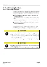
Страница 80: ...ump will stop operating automatically As a result the circulating fluid maintains a temperature of between 3 and 5 preventing freezing If the anti freezing function is set RUN lamp flashes for 2 sec during waiting pump does not operate The RUN lamp flashes at 0 3 sec intervals during the automatic operation of the pump The default setting of this function is OFF This function starts in stand by co...

Страница 81: ...ox 2 sec Repeat pressing the key until the setting screen for key lock appears on the digital display Anti freezing Setting and checking 2 Press the SEL key 9 times The set screen of anti freezing is displayed on the digital display 3 Select anti freezing from the table below with key or key and confirm by pressing SEL Table 5 11 2 List of set value Set value Explanation Initial value Default sett...

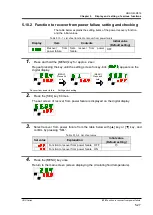
Страница 82: ...t setting Key click sound Sets key click sound ON 1 Press and hold the MENU key for approx 2 sec Repeat pressing the key until the setting screen for key lock appears on the digital display Key click sound Setting and checking 2 Press the SEL key 10 times The set screen of key click sound is displayed on the digital display 3 Select key click sound from the table below with key or key and confirm ...

Страница 83: ...et temperature unit switching Display Item Contents Initial value Default setting Temperature unit Sets temperature unit o C 1 Press and hold the MENU key for approx 2 sec Repeat pressing the key until the setting screen for key lock appears on the digital display Temperature unit Setting and checking 2 Press the SEL key 11 times The set screen of temperature unit is displayed on the digital displ...

Страница 84: ...re unit switching Display Item Contents Initial value Default setting Pressure unit Sets pressure unit MPa 1 Press and hold the MENU key for approx 2 sec Repeat pressing the key until the setting screen for key lock appears on the digital display Pressure unit Setting and checking 2 Press the SEL key 12 times The set screen of pressure unit is displayed on the digital display 3 Select pressure uni...

Страница 85: ...em Contents Initial value Default setting Alarm buzzer sound Sets alarm buzzer sound ON 1 Press and hold the MENU key for approx 2 sec Repeat pressing the key until the setting screen for alarm buzzer sound appears on the digital display Alarm buzzer sound Setting and checking 2 Select alarm buzzer sound from the table below with key or key and confirm by pressing SEL Table 5 15 2 List of set valu...

Страница 86: ...4 Circulating fluid discharge temp Refer to Table 5 16 6 and Table 5 16 7 Operation When this alarm signal is output user can choose to stop continue operation or not to detect this alarm Operation continue is default setting Threshold change Temp setting at which the alarm is generated can be changed and also the alarm generating conditions can be set 1 0 o C is default setting AL08 Circulating f...

Страница 87: ...can choose to stop continue the operation Operation stop is default setting AL33 Water leakage Refer to Table 5 16 17 Operation When this alarm signal is output user can choose to stop continue the operation Operation stop is default setting AL34 Electric resistivity conductivity rise Refer to Table 5 16 18 Operation When this alarm signal is output user can choose to continue operation or not to ...

Страница 88: ...tection pressure for the alarm of alarm NO AL08 circulating fluid discharge pressure rise Alarm signal is generated when the pressure becomes higher than this pressure 0 30MPa 44PSI Changing of circulating fluid discharge pressure drop Set the operation when alarm No AL09 circulating fluid discharge pressure drop is generated A RUN Detection pressure for circulating fluid discharge pressure drop S...

Страница 89: ... time Range over Detection timer After starting the alarm monitoring the alarm will not be generated right away and will be kept not generated for the set period of time for AL04 Detection temp for the circulating fluid discharge temp increase and AL06 Detection temp for circulating fluid discharge temp drop when the temperatures goes out of the set range 5 1 This function is available for custome...

Страница 90: ...ignal is generated Operation is stopped when this alarm signal is generated Detection temperature for circulating fluid discharge temperature rise Setting and checking 6 Press the SEL key once The set screen of detection temperature for circulating fluid discharge temperature rise is displayed on the digital display 7 Select detection temperature for circulating fluid discharge temperature rise fr...

Страница 91: ...pped when this alarm signal is generated Detection temperature for circulating fluid discharge temperature drop Setting and checking 10 Press the SEL key once The set screen of detection temperature for circulating fluid discharge temperature drop is displayed on the digital display 11 Select detection temperature for circulating fluid discharge temperature drop from the table below with key or ke...

Страница 92: ...e rise Setting and checking 14 Press the SEL key once The set screen of detection temperature for circulating fluid discharge pressure rise is displayed on the digital display 15 Select detection temperature for circulating fluid discharge pressure rise from the table below with key or key and confirm by pressing SEL Table 5 16 9 List of set value Set value Explanation Initial value Default settin...

Страница 93: ...re for circulating fluid discharge pressure drop Setting and checking 18 Press the SEL key once The set screen of detection temperature for circulating fluid discharge pressure drop is displayed on the digital display 19 Select detection temperature for circulating fluid discharge pressure drop from the table below with key or key and confirm by pressing SEL Table 5 16 11 List of set value Set val...

Страница 94: ...ted Operation is stopped when this alarm signal is generated The monitoring time of communication error Setting and checking 22 Press the SEL key once The set screen of the monitoring time of communication error is displayed on the digital display 23 Select the monitoring time of communication error from the table below with key or key and confirm by pressing SEL Table 5 16 13 List of set value Se...

Страница 95: ...nal 2 detection Setting and checking 26 Press the SEL key once The set screen of the changing of contact input signal 2 detection is displayed on the digital display 27 Select the changing of contact input signal 2 detection from the table below with key or key and confirm by pressing SEL Table 5 16 15 List of set value Set value Explanation Initial value Default setting This alarm signal is not d...

Страница 96: ...The set screen of the changing of water leakage is displayed on the digital display 31 Select the changing of water leakage from the table below with key or key and confirm by pressing SEL Table 5 16 17 List of set value Set value Explanation Initial value Default setting Setting checking are not available if the setting of the water leakage option is OFF Operation continues when this alarm signal...

Страница 97: ...he digital display 35 Select the changing of upper limit of electric resistivity conductivity rise with key or key and confirm by pressing SEL Refer to the Operation Manual attached to these optional accessories for details Changing of electric resistivity conductivity drop Setting and checking 36 Press the SEL key once The set screen of the changing of electric resistivity conductivity drop is di...

Страница 98: ...ting Continuous monitoring Alarm monitoring starts at the same time as operation starts Automatic monitoring When the circulating fluid temperature is outside of the alarm threshold range at the time of operation start the alarm will not be generated until the temperature comes inside the alarm threshold range Monitoring start timer Alarm will not be generated until it reaches the time set for the...

Страница 99: ...it is 1 minute Settings of this function and example of alarm generating timing for 5 15 3 Setting of temperature alarm monitoring method and generation timing Range over detection timer Setting and Checking 44 Press the SEL key once Setting screen of the range over detection timer is displayed on the digital display 45 Select range over detection timer from the table below with key or key and con...

Страница 100: ...n As the circulating fluid temperature at this time is 20 o C AS 06 starts alarm monitoring at the same time as the operation start Status 2 The circulating fluid temperature becomes within the set range of AS 04 and starts AS 04 alarm monitoring Status 3 The circulating fluid temperature exceeds the threshold of AS 06 but the alarm will not be generated as it has returned within the 600 sec range...

Страница 101: ...erature becomes within the set range of AS 04 AS 04 alarm monitoring starts Status 3 The circulating fluid temperature exceeds the threshold of AS 06 but the alarm will not be generated as it has returned within the 600 sec range of the AS 23 Range over detecting timer Status 4 The circulating fluid temperature exceeds the threshold of AS 04 but the alarm will not be generated as it has returned w...

Страница 102: ...ulated operation time is not reset NO 1 Press and hold the MENU key for approx 2 sec Repeat pressing the key until the setting screen for key lock appears on the digital display Data reset 2 Press the SEL key 13 times The set screen of data reset is displayed on the digital display 3 Select from the table below with key or key and confirm by pressing SEL Select then all data returns to default set...

Страница 103: ...lated time reset function The table below explains the setting items of the accumulated time reset and the initial values Table 5 18 1 List of set accumulated time reset function Display Item Contents Initial value Default setting Pump accumulated operating time reset Reset the accumulated operating time of the pump NO Fan motor accumulated operating time reset Reset the accumulated operating time...

Страница 104: ...below with key or key and confirm by pressing SEL Select then the accumulated operating time of the fan motor is reset The display returns to the main menu Table 5 18 3 List of set value Set value Explanation Initial value Default setting Not possible to reset Not reset Fan motor accumulated operating time is reset Compressor accumulated operating time reset 6 Press the SEL key once The set screen...

Страница 105: ...on range RW Contact input output communication Contact input signal 1 Sets contact input signal 1 RUN Contact input signal 1 type Sets input type of contact input signal 1 ALT Contact input signal 1 Delay timer time delay of reading Sets the delay timer of reading of contact input signal 1 0 Contact input signal 1 OFF detection timer Sets the contact input signal 1 OFF detection timer 0 Contact in...

Страница 106: ...panel operates and sets the thermo chiller Sets DIO mode 1 The operation starts with contact input output Sets SERIAL mode 2 Serial communication performs operation setting 1 When the setting of the contact input 1 is External switch signal DIO mode cannot be set 2 If the serial protocol is Simple communication protocol 2 and the contact input 1 is external switch signal or contact input 2 is remo...

Страница 107: ... specification Setting and checking 5 Press the SEL key once The set screen of communication specification is displayed on the digital display 6 Select communication specification from the table below with key or key and confirm by pressing SEL Table 5 19 4 List of set value Set value Explanation Initial value Default setting RS 232C RS 485 RS 485 terminal Setting and checking 7 Press the SEL key ...

Страница 108: ...DBUS to Sets of slave addresses for MODBUS Set range is 1 to 99 Communication speed MODBUS Setting and checking 11 Press the SEL key once The set screen of communication speed MODBUS is displayed on the digital display 12 Select communication speed MODBUS from the table below with key or key and confirm by pressing SEL Table 5 19 7 List of set value Set value Explanation Initial value Default sett...

Страница 109: ...speed simple communication protocol Setting checking 15 Press the SEL key once The set screen of communication speed simple communication protocol is displayed on the digital display 16 Select communication speed simple communication protocol from the table below with key or key and confirm by pressing SEL Table 5 19 9 List of set value Set value Explanation Initial value Default setting Setting c...

Страница 110: ...l Setting and checking 19 Press the SEL key once The set screen of data length simple communication protocol is displayed on the digital display 20 Select data length simple communication protocol from the table below with key or key and confirm by pressing SEL Table 5 19 11 List of set value Set value Explanation Initial value Default setting Setting checking are not available unless the serial p...

Страница 111: ...rotocol Setting and checking 23 Press the SEL key once The set screen of stop bit simple communication protocol is displayed on the digital display 24 Select stop bit simple communication protocol from the table below with key or key and confirm by pressing SEL Table 5 19 13 List of set value Set value Explanation Initial value Default setting Setting checking are not available unless the serial p...

Страница 112: ...e communication protocol Setting and checking 27 Press the SEL key once The set screen of communication range simple communication protocol is displayed on the digital display 28 Select communication range simple communication protocol from the table below with key or key and confirm by pressing SEL Table 5 19 15 List of set value Set value Explanation Initial value Default setting Setting checkin...

Страница 113: ...communication protocol 2 External switch signal cannot be set Contact input signal 1 type Setting and checking 31 Press the SEL key once The set screen of contact input signal 1 type is displayed on the digital display 32 Select contact input signal 1 type from the table below with key or key and confirm by pressing SEL Table 5 19 17 List of set value Set value Explanation Initial value Default se...

Страница 114: ...gnal 1 OFF detection timer Setting and checking 35 Press the SEL key once The set screen of the contact input signal 1 OFF detection timer is displayed on the digital display 36 Select contact input signal 1 OFF detection timer from the table below with key or key and confirm by pressing SEL Table 5 19 19 List of set value Set value Explanation Initial value Default setting Setting and checking ar...

Страница 115: ...signal 2 type Setting and checking 39 Press the SEL key once The set screen of contact input signal 2 type is displayed on the digital display 40 Select contact input signal 2 type from the table below with key or key and confirm by pressing SEL Table 5 19 21 List of set value Set value Explanation Initial value Default setting Setting checking are not available if the setting of contact input sig...

Страница 116: ...FF detection timer Setting and checking 43 Press the SEL key once The set screen of contact input signal 2 OFF detection timer is displayed on the digital display 44 Select contact input signal 2 OFF detection timer from the table below with key or key and confirm by pressing SEL Table 5 19 23 List of set value Set value Explanation Initial value Default setting Setting and checking are not availa...

Страница 117: ...set status is output Signal for Stop timer set status is output Signal for the recovery from power failure is output Signal for anti freezing setting is output Pass through signal of contact input signal 1 Pass through signal of contact input signal 2 Signal output during automatic fluid filling Contact output signal 1 operation Setting and checking 47 Press the SEL key once The set screen of cont...

Страница 118: ...contact output signal 2 function from the table below with key or key and confirm by pressing SEL Table 5 19 27 List of set value Set value Explanation Initial value Default setting Without output signal Signal of operating status is output Signal of remote status is output Signal for completion of preparation TEMP READY Signal for the status of the operation stop alarm is output Signal for the st...

Страница 119: ...al 2 selected alarm Setting and checking 55 Press the SEL key once The set screen of contact output signal 2 selected alarm is displayed on the digital display 56 Select contact output signal 2 selected alarm from the table below with key or key and confirm by pressing SEL Table 5 19 29 List of set value Set value Explanation Initial value Default setting Setting checking are not available unless ...

Страница 120: ...set status is output Signal for Stop timer set status is output Signal for the recovery from power failure is output Signal for anti freezing setting is output Pass through signal of contact input signal 1 Pass through signal of contact input signal 2 Signal output during automatic fluid filling Contact output signal 3 operation Setting and checking 59 Press the SEL key once The set screen of cont...

Страница 121: ...key and confirm by pressing SEL Table 5 19 32 List of set value Set value Explanation Initial value Default setting Setting checking are not available unless the function setting of digial output 3 is selected alarm status signal to Sets selected alarm Set range is AL 01 to AL 36 63 Press the MENU key once Return to the main screen screen displaying the circulating fluid temperature PV SV ...

Страница 122: ...HRX OM R016 Chapter 5 Display and setting of various functions 5 19 Communication function HRS Series 5 70 ...

Страница 123: ... stops does not start Code Description Code Description AL02 High circulating fluid discharge temp AL17 Refrigerant circuit pressure low pressure side drop AL05 High circulating fluid return temp AL18 Compressor overload AL06 High circulating fluid discharge pressure AL20 Memory error AL07 Abnormal pump operation AL22 Circulating fluid discharge temp sensor failure AL10 High compressor intake temp...

Страница 124: ...recommended preventive maintenance hours Please contact to service center to ask for maintenance of the pump and mechanical seal HRS012 018 10 T MT HRS012 018 024 030 20 T HRS012 018 024 030 20 MTNote 1 Rated flow 50 60Hz Note 2 3 7 0 36MPa 10 0 42MPa 10 0 44MPa 14 0 40MPa 10 0 32MPa 14 0 32MPa Maximum flow rate 50 60 Hz L min Maximum pump head 50 60 Hz m 55 70 60 Output W 320 A 15 A W Note 1 MT A...

Страница 125: ...vity sensor set 6 4 1 Optional Accessories Electric resistivity conductivity sensor set This function is available for customers who have purchased the electric resistivity conductivity sensor set which is a separately sold accessory Refer to the Operation Manual attached to these optional accessories for details Fig 6 4 1 Optional Accessories Electric resistivity conductivity sensor set ...

Страница 126: ...ed by this function AL33 Leakage is generated when water leakage is detected It is possible to set the operation when the alarm is generated Refer to the 5 15 Alarm customize function for details Fig 6 5 1 Optional Accessories Drain pan set Drain pan Water leakage detector Alarm AL33 Fluid leakage be generated if this setting is valid with the water leakage detector not being connected Make this s...

Страница 127: ...rox 2 sec Repeat pressing the key until the setting screen for key lock appears on the digital display Drain pan set Option Setting and checking 2 Press the SEL key 17 times The set screen of drain pan set Optional Accessories is displayed on the digital display 3 Select drain pan set Optional Accessories from the table below with key or key and confirm by pressing SEL Table 6 5 2 List of set valu...

Страница 128: ...HRX OM R016 Chapter 6 Option Optional Accessories 6 5 Optional Accessories Drain pan set HRS Series 6 6 ...

Страница 129: ...tion Manual for communication for details Read alarm status with serial communication Refer to the Operation Manual for communication for details The thermo chiller has two types of operation depending on the alarm status One alarm type will stop operation when an alarm is generated during operation The other type will not stop operation even when an alarm is generated Refer to the Table 7 1 Alarm...

Страница 130: ...larm with the highest number is the alarm that was generated first Example of display The temperature rises gradually and alarms are generated in the order AL03 AL06 AL02 The alarm code displayed on the operation panel is AL02 AL06 AL03 are displayed by pressing the SEL key Digital display SV displays 3 when AL03 is displayed In this example AL03 is the highest number This means AL03 is the alarm ...

Страница 131: ...screen Press and keys down simultaneously The alarm buzzer is stopped Tips The alarm buzzer can be set not to make sound Refer to 5 15 Alarm buzzer sound setting The procedure to stop the alarm buzzer is not necessary when the buzzer is set not to make a sound If this procedure is performed when the cause of the alarm has been eliminated before stopping the alarm buzzer the alarm will be reset at ...

Страница 132: ...ting the cause of the alarm Ensure that the alarm display screen is displayed Alarm can only be reset on this screen Press and keys down simultaneously The alarm is reset The ALARM lamp goes off The operation panel displays the circulating fluid temperature and the circulating fluid set temperature The contact signal of the contact input output communication stops Refer to the Operation Manual for...

Страница 133: ...n the evaporator is not frozen Use a 15 ethylene glycol aqueous solution if operating with a set temperature lower than 10 o C AL12 Low super heat temperature Stop AL13 High compressor discharge pressure Stop Reduce the ambient temperature or heat load AL15 Refrigerant circuit pressure high pressure side drop Stop Check the ambient temperature is within the specified range It is possible that refr...

Страница 134: ...y conductivity sensor Replace the sensor 1 Stop or Continued are default settings The user can change them to Continued and Stop For details refer to 5 16 Alarm customize function 2 AL19 Communication error is disabled in the default setting When this function needs to be enabled refer to 5 19 Communication function 3 For air cooled type 4 The functions of AL31 Contact input 1 Signal detection and...

Страница 135: ...0 or less Copper mg L 0 1 or less 0 3 or less Sulfide ion mg L Not detected Not detected Ammonium ion mg L 0 1 or less 1 0 or less Residual chlorine mg L 0 3 or less 0 3 or less Separation carbonic acid mg L 4 0 or less 4 0 or less Quoted from JRA GL 02 1994 The Japan Refrigeration and Air Conditioning Industry Association Use specified circulating fluids only If other fluids are used they may dam...

Страница 136: ...or use Operating conditions Check the operation condition There is no abnormal noise vibration smell and smoke There should be no active alarm signal Ventilating condition For air cooled type Check the condition of the ventilation grille Make sure the ventilation grille is not obstructed Facility water supply For water cooled type Check the supply condition to the thermo chiller Temperature flow r...

Страница 137: ...ed or damaged Removal of the dustproof filter 1 The dustproof filter is installed at the lower part of the front face of the thermo chiller It is mounted with a magnet Pull out the lower part of the side surface of the dustproof filter 2 When the magnet comes off pull the dustproof filter downwards to remove Care should be taken not to deform or scratch the air cooled condenser Fig 8 1 Removal of ...

Страница 138: ...ater periodically Clean the tank Ensure that the water has not been contaminated and that there is no algae growth Circulating water inside the tank must be clean and there must not be foreign matter inside Use clean water or pure water The water quality must be within the range shown in Table 8 1 It is recommended to replace the circulating fluid every 3 months when periodic maintenance is perfor...

Страница 139: ...r select from the specification range shown in Table 8 1 Quality standard for fresh water tap water 8 2 4 Inspection every 6 months Check for water leakage from pump For option T High head pump Remove the panel and check the pump for excessive leakage If the leakage is found replace the mechanical seal Order the mechanical seal described in 8 3 Consumables as a service part Leakage from the mechan...

Страница 140: ...01 Dustproof filter 1 For spare HRG S0211 Mechanical seal set 1 For option T High head pump This function cannot prevent freezing of the product completely if the installation area is exposed to severe cold weather conditions In such conditions consult with a specialized vendor to install other anti freezing equipment commercial tape heater etc Also the facility water circuit does not have a simil...

Страница 141: ... and facility water from the product 2 Remove the tank lid 3 Remove the drain plug on the drain port on the piping to discharge the fluid An O ring is used for the drain plug Take care not to damage the O ring 4 Confirm that a sufficient amount of the circulating fluid has been drained from the user s machine and piping and apply air purge from the circulating fluid return port 5 After discharging...

Страница 142: ...completely discharged apply the sealant tape to the plugs which are removed during step 7 for mounting Mount the dustproof filter after mounting them Please refer P8 4 for how to mount 9 Refer to Fig 8 6 to mount the plug to the piping of the product Fig 8 6 Plug to the piping of the product Circulating fluid outlet Rc1 2 Circulating fluid return port Rc1 2 Plug Plug Facility water outlet Rc3 8 Fo...

Страница 143: ...t Accessories Fig 8 8 Example of using fitting for the drain port Option T High head pump The ball valve is the drain port Open the ball valve to discharge the circulating fluid in the same way as procedure 1 to 9 Close the ball valve after discharging the circulating fluid Fig 8 9 Drain the circulating fluid and facility water from the product for option T High head pump O ring Rc3 8 Example Drai...

Страница 144: ...HRX OM R016 Chapter 8 Control Inspection and Cleaning 8 4 Stop for a Long Time HRS Series 8 10 ...

Страница 145: ... 1pc Quick manual with a clear cover 1pc Alarm code list label 1pc Weight 12 kg 47 46 1 For water cooled type 2 Use the product in conditions where freezing will not occur Consult with SMC if using in a season or region where the ambient temperature will fall below zero 3 If tap water is used use water which satisfies the standard of The Japan Refregeration And Air Conditioning Industry Associatio...

Страница 146: ... Potential GWP Regulation EU No 517 2014 Based on the IPCC AR4 Revised Fluorocarbons Recovery and Destruction Law Japanese law R134a 1 430 1 430 R404A 3 922 3 920 R407C 1 774 1 770 R410A 2 088 2 090 Note 1 This product is hermetically sealed and contains fluorinated greenhouse gases 2 See specification table for refrigerant used in the product ...

Страница 147: ...esistance load Minimum load current DC5V 10mA Output voltage DC24V 10 0 5A MAX Circuit structure diagram Serial communication Table 9 4 Specifications List Item Specification Connector type for this product D sub9 pin Female connector Protocol Modicon Modbus standard Simple communicationprotocol Standard EIA RS 485 EIA RS 232C Circuit structure diagram 4 7kΩ This product Your system Internal circu...

Страница 148: ...ower cable hole Drain port With plug Circulating fluid return port Rc1 2 Circulating fluid outlet port Rc1 2 Model no label Facility water outlet Rc3 8 For water cooled type Optuon B Earth leakage breaker Drain port Rc1 4 Option T High head pump specifications Option J Automatic water fill specifications Automatic water fill port Rc3 8 Overflow port Rc3 4 Vent hole Same vent hole locates on the op...

Страница 149: ...uid filling port Rc3 8 Over flow port Rc3 4 Air cooled condenser Heat exchanger Automatic fluid filling circuit For option with automatic fluid filling J Circulating fluid circuit Refrigeration circuit Tank Level switch Comp Presssensor for high pressure Expansion1 Expansion2 Tempsensor Presssensor for low pressure Temp sensor for return port Pump Press sensor for outlet Tempsensor foroutlet Circu...

Страница 150: ...0 4000 0 10 20 30 40 50 Circulating fluid temperature Cooling capacity W 25 32 40 Ambient temperature or facility water temperature Ambient temperature or facility water temperature 50Hz 60Hz 50Hz 0 200 400 600 800 1000 5 10 15 20 25 30 35 40 Circulating fluid temperature Heating capacity W 40 32 25 20 5 60Hz 0 200 400 600 800 1000 5 10 15 20 25 30 35 40 Circulating fluid temperature Heating capac...

Страница 151: ...0 1 0 2 0 3 0 10 20 30 Circulating fluid flow L min Circulating fluid pressure MPa Outlet 50Hz Return port 5 Availavel area Min neccesary flow 5L min Outlet 60Hz 10 20 Pump head m 5 0 0 0 1 0 2 0 3 0 4 0 5 0 6 0 7 0 8 0 5 10 15 20 25 Circulating fluid flow L min Circulating fluid pressure MPa Return port Availavel area Outret 60Hz Outlet 50Hz Availavel area Pump head m 10 20 60 30 40 50 70 0 80 ...

Страница 152: ...r cooled type 0 0 0 1 0 2 0 3 0 4 0 5 0 6 0 7 0 8 0 5 10 15 20 25 Circulating fluid flow L min Circulating fluid pressure MPa Availavel area Return port Availavel area Pump head m 10 20 60 30 40 50 70 0 80 Outlet 50Hz Outlet 60Hz 0 5 10 15 20 25 30 0 10 20 30 40 50 Facility water inlet temperature Facility water flow rate L min The amount of the facility water for the operation with rated circulat...

Страница 153: ...er 9 Documents HRS Series 9 8 Compliance 9 9 9 8 Compliance This system conforms to the following standards Table 9 2 Compliance CE Marking EMC Directive 2004 108 EC Machinery Directive 2006 42 EC NRTL E112803 UL61010 1 ...

Страница 154: ...ssy Saint Georges F 77600 Germany SMC Pneumatik GmbH 49 6103 402 0 Boschring 13 15 D 63329 Egelsbach Greece SMC Hellas E P E 30 210 2717265 Anagenniseos 7 9 P C 14342 Nea Philadelphia Athens Hungary SMC Hungary Ipari Automatizálási Kft 36 23 511 390 Torbágy u 19 HU 2045 Törökbálint Ireland SMC Pneumatics Ireland Ltd 353 1 403 9000 2002 Citywest Business Campus Naas Road Saggart Co Dublin Italy SMC...

Страница 155: ...tart right after setting up Thermo chiller Daily Check Sheet Inlet pressure MPa Flow rate L min Temperature Operation conditions Presence of error Present Not present Circulating fluid temp Fluid amount Inside Outside of liquid level Inside Outside Fluid leakage Humidity Temperature Right after setting up Result Facility water For water cooled type Operation Display Operation panel Setting up cond...

Страница 156: ...HRX OM R016 Chapter 9 Documents 9 10 Daily Check Sheet HRS Series 9 12 ...

Страница 157: ...he failure was a secondary failure of the product caused by the failure of equipment connected to the product 6 The failure was caused by a natural disaster such as an earthquake typhoon or flood or by an accident or fire 7 The failure was caused by operation different from that shown in the Operation Manual or outside of the specifications 8 The checks and maintenance specified daily checks and r...

Страница 158: ...form checks and maintenance daily checks and regular checks specified in the Operation Manual and Maintenance Manual 3 Record the check and maintenance results on the daily check sheet attached to the Operation Manual and Maintenance Manual 7 Request for Warranted Repair For warranted repair please contact the supplier you purchased this product from Warranted repair shall be on a request basis Re...

Страница 159: ......

Страница 160: ... 101 0021 JAPAN Tel 81 3 5207 8249 Fax 81 3 5298 5362 URL http www smcworld com Note Specifications are subject to change without prior notice and any obligation on the part of the manufacturer 2017 SMC Corporation All Rights Reserved ...

Отзывы: