8
SVC400P/SVC800P - Installation Manual
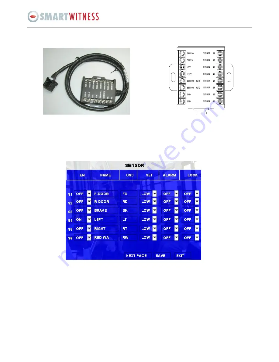
9.2 Specifications for the SENSOR BOX (sensor inputs and outputs)
SENSORs 1-6 are the inputs for I/O sensors,
SENSOR OUT is for sensor output connection
SPEED- and SPEND+ are for speed sensor, which connect to the speed pulse of the vehicle.
Firstly, follow the steps of GUI > SETUP > EVENT > SENSOR; then, enable the sensor switch; and make sure the alarm switch is
ON, as shown below:
The MDVR has 6 Alarm inputs and 2 Alarm outputs. All alarm inputs are I/O PWL which can reflect various vehicle statuses such
as braking, turning left etc. A schematic diagram of the alarm input ‘braking’ is shown below; when the brake is applied the
MDVR will detect the I/O PWL, the alarm LED will light up (or flash) and will record this event.


