background image


SVC400P/SVC800P - Installation Manual 


7. INSTALLATION INSTRUCTIONS 

Follow these guidelines when installing MDVR’s: 


Unpack all components provided in the package. 


Disconnect any source of power supply and/or devices. 


Locate a proper spot to install the SVA400L and install a built-in vibration absorber if required. 


Locate a reliable electrical ground point in the vehicle. 


All wires and connections should be gathered to the back of SVA400L. 


Connect to a power source and turn on the vehicle ignition to test the unit. 


Observe completion of the unit power-up procedures as described in section labelled as "System Startup and 
Shutdown". 


Meet all legal requirements for installing and/or operating a video surveillance, such as labelling all the essential 
information on the MDVR. Video surveillance statues vary across nations; please abide to the local statues. 

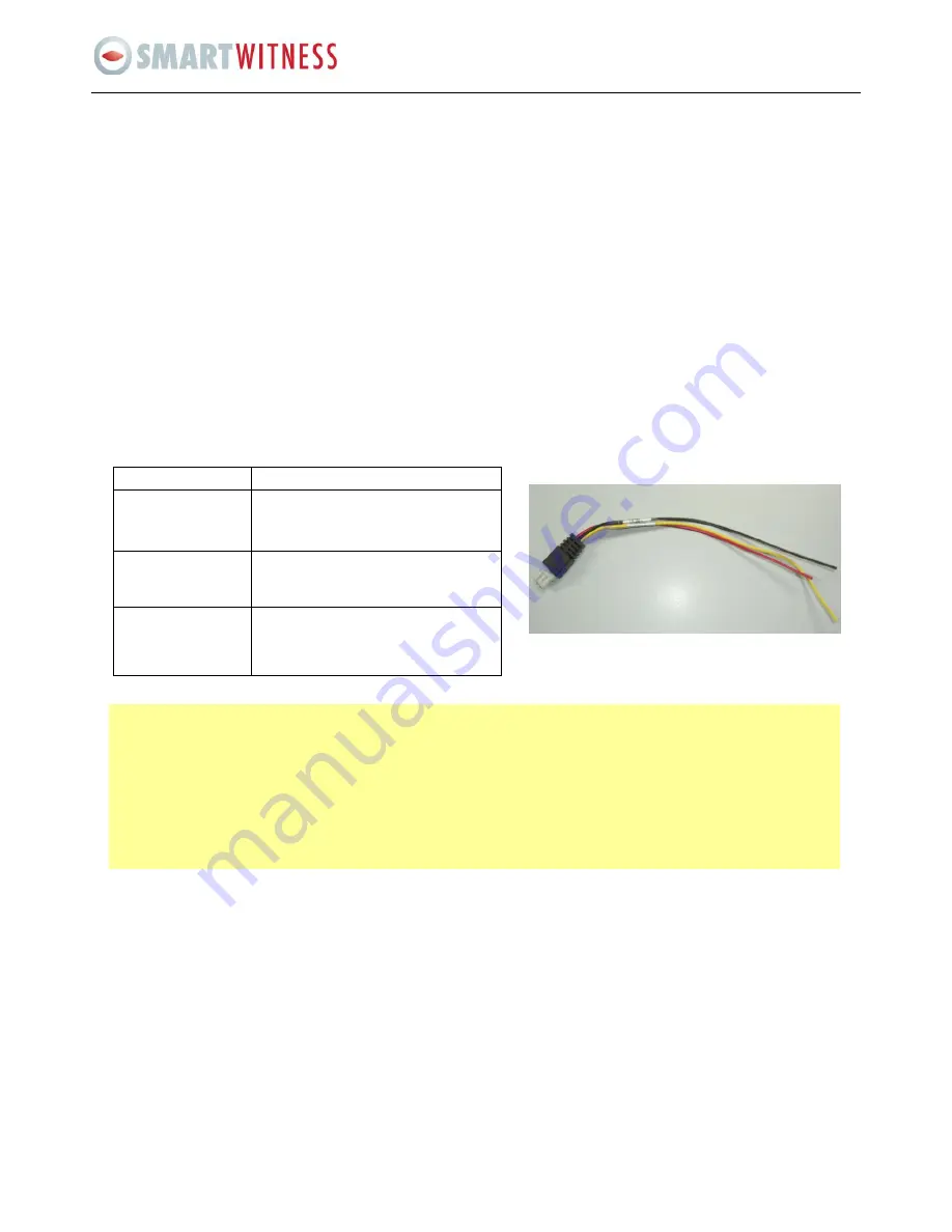
8. CONNECTING THE POWER FOR THE MDVR’S 


Wire 

Description 

Positive Input (Red) 

Positive wire. Should be connected to 
the positive terminal of the battery (DC 
+12V) 

GND Input (Black) 

Negative (ground) wire. Should be 
connected to the negative terminal of 
the battery. 

Ignition Signal Input 
(Yellow) 

Connect with vehicle ignition to let the 
system start up (need provide 
+12V/24V DC power as signal ON/OFF) 

The Ignition Switch is very important. Only once the MDVR’s is to the ignition wire can it can boot up  

The following conditions must be fulfilled at the same time for MDVR’S to boot up: 

1.


If you don’t use ignition line, please connect it to positive terminal, otherwise the device can’t startup. 

2.


Make sure the HDD installation is correct, since the MDVR will try to detect the HDD first before boot up. If the 
HDD installation is wrong, then the unit will continuously try to detect the HDD and MDVR’s will not complete 
the boot-up process. 


Содержание SVC400P

Страница 1: ...SVC400P SVC800P 4 8 Camera Live Tracking Vehicle DVR Installation Manual Version 1 0 ...

Страница 2: ... TOOLS 5 7 INSTALLATION INSTRUCTIONS 6 8 CONNECTING THE POWER 6 9 CONNECTING INPUTS AND OUTPUTS 7 9 1 The A V Cable Definition Video Input AV output 7 9 2 Specifications for the SENSOR BOX sensor inputs and outputs 8 9 3 Specifications for 485 and 232 serial ports 9 10 WORKING STATUS 10 11 INERTIAL SENSOR CONNECTION 11 12 HDD INSTALLATION 11 13 SIM CARD INSTALLATION 12 ...

Страница 3: ...itionally the MDVR s CMS is set up to provide automatic services for the protection of its data such as recovery data monitoring and backup for all its critical data 2 PRODUCT OVERVIEW Front View Definition for LED and connector on front panel Items Name Description Video Output VIDEO_OUT Video output LED HTR Heater LED SD Flash when the SD is writing and reading REC for record ON means recording ...

Страница 4: ...e and then MDVR will standby Rear View Items Name Description WI FI ANT connector WI FI For connecting the WIFI ANT GPS ANT connector GPS For connecting the GPS ANT 3G EDGE GPRS ANT connector EDGE For connecting the 3G EDGE GPRS ANT Power input DC8 48V For connecting power input Network port RJ45 Network port to make sure the MDVR can go online A V Integrated input A V A V input and output and ala...

Страница 5: ...4 SVC400P SVC800P Installation Manual 3 DIMENSIONS ...

Страница 6: ...tall where unit temperature will exceed F140 F 60 C fall below 20 F 28 C or store the unit where temperatures rise above 175 F 80 C Avoid direct exposure to sunlight Ventilation Provide sufficient ventilation with a minimum of 6 inches cooling clearance to ensure proper operating temperature for the unit Vibration If necessary provide additional shock mounting to prevent damage and wear by excessi...

Страница 7: ...nce statues vary across nations please abide to the local statues 8 CONNECTING THE POWER FOR THE MDVR S Wire Description Positive Input Red Positive wire Should be connected to the positive terminal of the battery DC 12V GND Input Black Negative ground wire Should be connected to the negative terminal of the battery Ignition Signal Input Yellow Connect with vehicle ignition to let the system start...

Страница 8: ... Explanation A V INPUT VIN1 VIN4 A V input is a 4 pin female connector 4CH machine has 4 A V inputs 8CH machine has 8 A V inputs Feet 1 is for 12V power input feet 2 is for GND feet 3 is for audio input and feet 4 is for video input A V OUTPUT AV OUT A V output is a 4 pin male connector feet 1 is for 12V power input feet 2 is for GND feet 3 is for audio input and feet 4 is for video input ...

Страница 9: ...e Firstly follow the steps of GUI SETUP EVENT SENSOR then enable the sensor switch and make sure the alarm switch is ON as shown below The MDVR has 6 Alarm inputs and 2 Alarm outputs All alarm inputs are I O PWL which can reflect various vehicle statuses such as braking turning left etc A schematic diagram of the alarm input braking is shown below when the brake is applied the MDVR will detect the...

Страница 10: ...aming Video Technology such as the inertia sensor acceleration control panel PTZ station announcement and the card reader etc Please Note 485A means 485 485B means 485 SETUP PERIPHERAL EXT COM SETUP MODE There are STANDARD and BUS MODE two options when select standard mode you can select each external port for each COM when select Bus mode COM1 is station announcement COM2 is amplifier board uncha...

Страница 11: ...N means there is no HDD or some other hardware errors NET is ON means the net module is normal VIDEO LOSS is ON means there is video loss if all the LED always flashing and no live view that means there is something wrong with MDVR please contact with the sales Please Note when MDVR has started up and only POWER LED is on and no live view output please make sure you have locked the HDD box ...

Страница 12: ...DD box and screws and then open the box as the picture below Install the foam pad on both sides Since there is no screw here we are use rubber cover and foam pad as a vibration absorber One side of the box is a blue foam pad the other side is two yellow foam pads Put the rubber cover on both sides of the SATA HDD the side with a rubber band should be near to the circuit board Connect the cable ple...

Страница 13: ...DD box and the SIM Card cover Carefully insert the SIM card in place re attach the SIM Card cover and place the screws and HDD box back as normal ensuring that you have connected the 3G antenna Follow the steps of GUI SETUP NETWORK MOBILE NETWORK select the mode type for the wireless module you have got as well as APN and the access number The device will restart after all these have been setup In...

Страница 14: ...p status Finally we can check the status of the SIM card by pressing ENTER in the live view after unit has restarted You will find the status information for unit see the screen below which includes signal network dial up status and CMS connection status ...

Отзывы: