SMA Solar Technology AG
2 Installation
Installation Manual
STP60-JP-10-IA-en-11
15
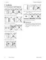
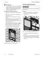
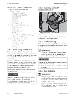
Figure 2.12 Hooking the inverter into the wall mounting bracket
5. Check that the four side screws sit securely in the wall
mounting bracket slots.
6. Release the inverter.
2.4 Disassembling the Inverter
Procedure:
1. Disassemble the inverter in the reverse mounting order.
2. Lift and slide the inverter out of the wall mounting
bracket slots.
3. Lift the inverter off the wall mounting bracket.
2.5 Access to the Installation Area
Procedure:
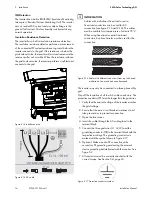
1. To open the cover, loosen the three lower front screws
using a TX 30 screwdriver. The screws are captive
screws and cannot fall out.
2. Open the cover and flap it back. A magnet enables the
cover to stay open.
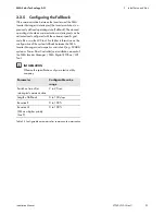
Figure 2.13 Loosen front screws and lift the cover
3. To close the cover, lower it into place and fasten the
three front screws.
2.6 AC Grid Connection
Before working on the inverter, disconnect it from the utility
grid by means of the AC breaker and switch off PV using
the integrated PV load-break switch (DC load-break
switch). Ensure that the inverter cannot be unintentionally
reconnected. Use a voltage detector to ensure that the
unit is disconnected and voltage free. The inverter can still
be charged with very high voltage at hazardous levels
even when it is disconnected from utility grid and PV
modules. Wait at least five minutes after disconnection
from the utility grid and PV modules before proceeding.
Observe ESD safety regulations. Discharge any
electrostatic charge by touching the grounded enclosure,
before handling any electronic component.
These instructions for AC grid connection are for qualified
personnel only. To reduce the risk of electric shock, do not
perform any maintenance work other than that specified
in the manual unless you are qualified to do so.
For fuse and RCD information, refer to Section
5, page 30. AC fuse rating must not exceed the ampacity
of the conductors used.

