6 Electrical Connection
SMA Solar Technology AG
Operating manual
47
SI44M-80H-13-BE-en-15
Procedure:
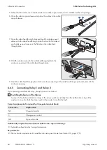
1.
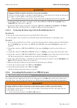
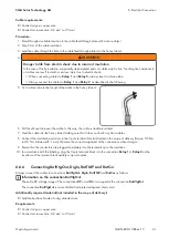
WARNING
Danger to life from electric shock due to incorrect insulation
In the case of faulty insulation, supposedly de-energized parts or cables may be live. Touching live components
or cables can result in death or serious injury due to electric shock.
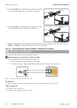
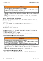
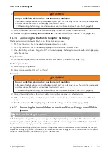
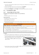
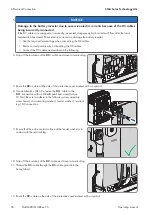
• When making the following connections, always insert a silicone tube (see Section 6.6.5, page 60).
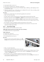
2. The default setting of the Sunny Island uses the multifunction relay
Relay1
for generator requests. Therefore,
connect the control cable to the multifunction relay
Relay1
on the Sunny Island. Use the
C
and
NO
connections.
3. If the multifunction relay
Relay1
for generator requests is not available, connect the control cable to the
multifunction relay
Relay2
on the Sunny Island. Use the
C
and
NO
connections.
4. If, with more than one Sunny Island, the multifunction relay
Relay1
and
Relay2
for generator requests are not
available on the Master, connect the control cable to a free multifunction relay on slave 1 or slave 2. Use the
C
and
NO
connections.
5. Enter the configuration
Automatic generator request
in the table of settings (see Section 7.10.2, page 102).
6.5.11 Connecting a Signaler for Generators Without an Autostart Function
Relevant for off-grid systems
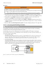
Generators without an autostart function do not have electric starting devices. If you install a generator without an
autostart function, you can connect a signal generator (e.g., signal lamp) to the multifunction relay of the Sunny Island
inverter. As a result, the Sunny Island can signal when the generator is to be manually started and stopped.
Signal generator or generator control in a cluster
Slaves control the generator less reliably than masters do.
• Connect the generator control preferably to the master.
• In a multicluster system, always connect the signal generator to the master of the main cluster.
PE
N
L
PE
N
L
NO
C
A
C1
A
C2
Relay
SUNNY ISLAND
PE
N
L
STAND-ALONE GRID
SIGNAL GENERATOR
EXTERNAL
GENERATOR
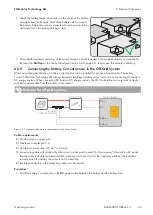
Figure 12: Connecting a Signal Generator to Signal a Generator Request (Example)
Requirements:
☐ The technical requirements of the multifunction relay must be met (see Section 16, page 175).
Cable requirements:
☐ Conductor type: copper wire
☐ Conductor cross-section: 0.2 mm² to 2.5 mm²


