22
2728
13
2021
-
SEP 80 & 100 & 120 & 130 & 150
MG_0062
Technical Wiring Diagram
EN
Страница 1: ...AS P O Box 519 N 1612 Fredrikstad Norway www sleipnergroup com DOCUMENT ID REVISION DATE LANGUAGE Installation Guide For Pro DC Electric Thruster Models SEP80 SEP100 SEP120 SEP130 SEP150 EN I M 2728...
Страница 2: ...nel installation 13 Thruster Installation Instructions Thruster Installation Considerations and Precautions 14 Gear Leg Motor Bracket Installation 15 Propeller Installation 16 Motor Installation 17 Th...
Страница 3: ...special national regulations Instructions in this guide cannot be guaranteed to comply with global electric mechanic regulations classi cation rules Follow all health and safety laws in accordance wit...
Страница 4: ...ommended Recommended tunnel length 216 8 50 216 8 50 216 8 50 216 8 50 276 10 87 303 11 93 303 11 93 T min Minimum tunnel wall thickness 6 0 24 6 0 24 6 0 24 6 0 24 7 0 28 7 0 28 7 0 28 T max Maximum...
Страница 5: ...all bearing at propeller shaft and a combination of ball bearing and slide bearing at drive shaft Pre lled and sealed for life Motor bracket Glass bre reinforced composite material Brass thread insert...
Страница 6: ...ster as deep as possible under the waterline 2 Deeper installations prevent air from being sucked into the tunnel from the surface resulting in reduced thrust performance and increase noise levels dur...
Страница 7: ...not allow the variable length of the tunnel walls to vary in length excessively EG the top tunnel wall is x 4 longer than the bottom wall 2 If the tunnel is too long the friction inside will reduce th...
Страница 8: ...nstead t the tunnel halfway into the underneath section of the existing hull Strengthen it with a deflector spoiler directing the water flow around the tunnel This will allow installation of the thrus...
Страница 9: ...it is angled slightly down because of the water flow on this area 2 3 Making a deflector spoiler in front and underneath the tunnel can also reduce damage to the thruster and drag The deflector spoile...
Страница 10: ...e tunnel and thereby reduces the effective tunnel diameter and thrust Turbulence cavitation on the propeller will lessen the thrusters performance and create excess noise 2 For steel aluminium hulls a...
Страница 11: ...l cover the back face 5 Cut the tunnel ends to the desired shape and lightly sand its surface Clean the area with acetone or similar where you are going to apply breglass NB Do not cast or add breglas...
Страница 12: ...h tunnel installed and cast 1 Round the edges with a radius of 10 of the tunnel diameter 2 For steel aluminium hulls make a slope with a length of 10 15 of the tunnel diameter NB If this is not possib...
Страница 13: ...nstallation please refer to the supplied manual in your Sleipner product delivery Stern Thruster SLEIPNER AS P O Box 519 N 1612 Fredrikstad Norway www sleipnergroup com DOCUMENT ID REVISION DATE LANGU...
Страница 14: ...special national regulations Instructions in this guide cannot be guaranteed to comply with global electric mechanic regulations classi cation rules Follow all health and safety laws in accordance wit...
Страница 15: ...e clearance from each blade to the tunnel wall Place top motor bracket to measure the drive shaft has come through the motor bracket at the correct height Remove the gear leg and propeller for nal ins...
Страница 16: ...he end of the shaft spline Tighten with the propeller lock nut 3 Insert the anode to the end of the propeller and tighten the anode holding screw Apply a thread glue Loctite 243 or similar to ensure t...
Страница 17: ...bracket with the above torque 4 Check the drive shafts are engaged by rotating the propeller NB Rotating the propellers can be hard due to the gear reduction and the motor however the propeller must b...
Страница 18: ...the electrical operation of the vessel when not on board or in emergencies NB It is advised to install a fuse on the positive cable for protection against short circuiting of the main cables The fuse...
Страница 19: ...0 NA NA NA AWG 2 0 2 0 4 0 2 x 2 0 2 x 3 0 2 x 3 0 2 x 4 0 2 x 4 0 2 x 4 0 24 V 280 A DIN 300 SAE 570 EN 520 ANL 250 mm2 35 35 35 50 50 70 70 95 95 120 120 2 x 95 AWG 2 2 2 1 0 1 0 2 0 2 0 3 0 3 0 4 0...
Страница 20: ...al Power Controller Automatic Main Switch 8977 12 8977 24 or Manual main switch w ANL fuse Automatic Main Switch 8977 12 8977 24 or Manual main switch w ANL fuse link control system End terminator End...
Страница 21: ...d to be as short as practically possible POWER Cable Must be one in each system length 2 5m 4 Port T Connector The 4 port T connector allows multiple spur cables to be connected NB Comes with two seal...
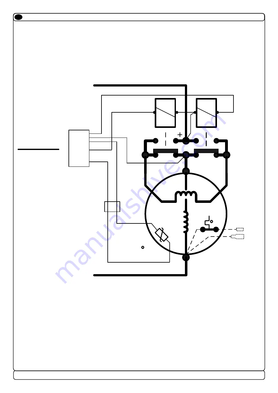
Страница 22: ...22 2728 13 2021 SEP 80 100 120 130 150 MG_0062 Technical Wiring Diagram EN...
Страница 23: ...lation EN For Control Panel installation please refer to the supplied manual in your Sleipner product delivery MC_0398 SLEIPNER AS P O Box 519 N 1612 Fredrikstad Norway www sleipnergroup com DOCUMENT...
Страница 24: ...he gear house and propeller but NOT anodes sealing rubber ttings or propeller shafts Propeller is fastened correctly to the shaft Propeller turns freely in tunnel The anode and or holding screw is tig...
Страница 25: ...ed to the Purchaser at the Warrantor s expense If on the other hand the claim is determined to result from circumstances such as described in section 4 above or a result of wear and tear exceeding tha...
Страница 26: ...26 2728 13 2021 SEP 80 100 120 130 150 MC_0037 Notes EN...
Страница 27: ...27 2728 13 2021 SEP 80 100 120 130 150 MC_0037 Notes EN...
Страница 28: ...accuracies or omissions it may contain Continuous product improvement may change the product speci cations without notice Therefore Sleipner Motor AS can not accept liability for any possible differen...