Sleipner Pro DC SEP210 Скачать руководство пользователя страница 21

 21

2713

20

2022

-

SEP 210

MG_0062

Technical Wiring Diagram

A1

A2

D2

NTC

Thruster motor

D1

1

2

3

4

5

6

7

8

To PPC

B+

To PPC

M-

Multi cable to PPC

grey

blue

white

red

pink

(Opt.)

8-Way connector

C

C

red or  

 red-brown

MC_0120

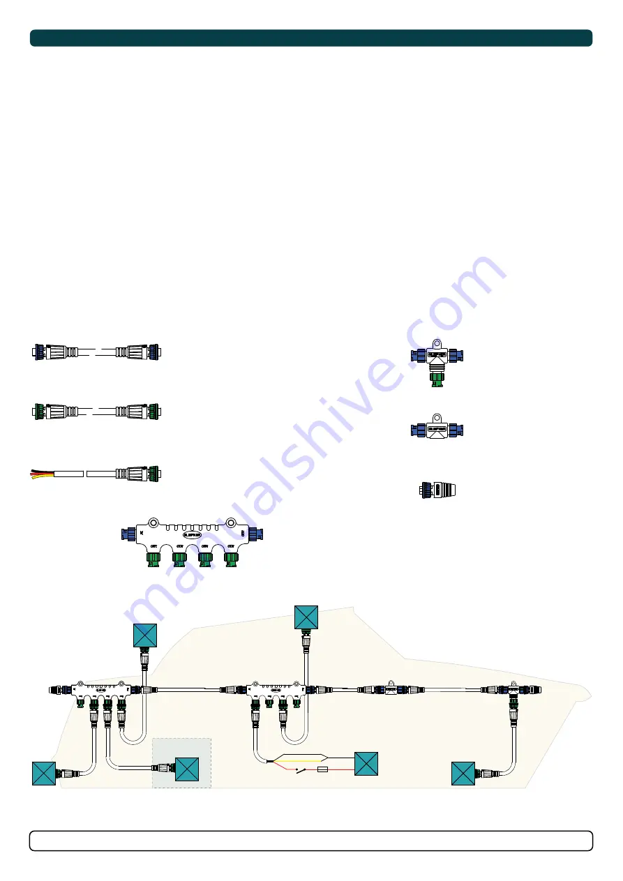
S-Link System Description

S-Link is a CAN-based control system used for communication between Sleipner products installed on a vessel. The system uses BACKBONE Cables 

as a common power and communication bus with separate SPUR Cables to each connected unit. Units with low power consumption are powered 

directly from the S-Link bus therefore one power cable must be connected to the BACKBONE Cable through a T-Connector. 


Main advantages of S-Link system:

-    Compact and waterproof plugs.

-    BACKBONE and SPUR Cables have different colour coding and keying to ensure correct and easy installation. BACKBONE Cables have blue  

  connectors and SPUR Cables have green connectors.

-    Different cable lengths and BACKBONE Extenders makes the system scalable and flexible to install. 

Installation of S-Link cables:

Select appropriate cables to keep the length of BACKBONE- and SPUR Cables to a minimum. In case of planned installation with total BACKBONE 

Cable length exceeding 100 meters please consult your local distributor. The S-Link cables should be installed to ensure sharp bend radius’s is 

avoided. Locking mechanism on connectors must be fully closed. To ensure long lifetime, cables, T-Connectors and Extenders should not be 

located so that they are permanently immersed in water or other fluids. It is also recommended to install cables such that water and condensation do 

not run along the cables and into the connectors.

The POWER Cable should ideally be connected around the middle of the BACKBONE Cable to ensure an equal voltage drop at each end of the 

BACKBONE Cable. The yellow and black wire in the POWER Cable shall be connected to GND and the red wire connected to +12VDC or +24VDC.

To reduce the risk of interference, avoid routing the S-Link cables close to equipment such as radio transmitters, antennas or high voltage cables. The 

backbone must be terminated at each end with the END Terminator.

SPUR cables can be left unterminated to prepare for the installation of future additional equipment. In such cases, ensure to protect open connectors 

from water and moisture to avoid corrosion in the connectors.

MG_0159

BACKBONE Cable

Forms the communication and power bus throughout 

a vessel. Available in different standard lengths.

*Blue ends

*Blue ends

*Blue ends

*Blue ends

*Blue ends

*Blue ends

*Blue ends

*Blue ends

*Blue ends

*Green ends

*Green ends

*Green ends

*Green ends

*Green ends

SPUR Cable

Used to connect S-Link compliant products to the 

backbone cable. One SPUR Cable must be used for 

each connected component, with no exceptions. 

Recommended to be as short as practically possible. 

Available in different standard lengths.

POWER Cable

Required in all installations for connection of BACKBONE 

Cable to a power supply. It shall not be more than one 

POWER Cable in an installation.

4-Port T-Connector

The 4-PORT T-connector allows multiple SPUR Cables to be 

connected. The 4-PORT T-connector comes with two sealing 

caps to protect unused ports.

T-Connector

Used for connection of SPUR 

or POWER Cable to the 

BACKBONE Cable. One 

T-Connector for each 

connected cable.

BACKBONE Extender

Connects two BACKBONE 

Cables to extend the length. 

END Terminator

Must be one at each end of 

the BACKBONE bus. 

12/24V

GND

Switch

Optional

Fuse

2A

S-Link installation example

Spur

Power

T-Connector

End 

Terminator

End 

Terminator

Backbone Extender

Bow Thruster

Control Panel

Spur

Control Panel

Backbone

Backbone

Backbone

Spur

Spur

*For DC system

Spur

4 Port T-Connector

4 Port T-Connector

Stern Thruster

Automatic 

Main switch

S-Link

Power Supply

Yellow

Red

Black

Содержание Pro DC SEP210

Страница 1: ...SLEIPNER AS P O Box 519 N 1612 Fredrikstad Norway www sleipnergroup com DOCUMENT ID REVISION DATE LANGUAGE Installation Guide For Pro DC Electric Thruster Models SEP210 EN I M 2713 20 2022...

Страница 2: ...he tunnel thruster 7 Tunnel Length 8 Tunnel installation in sail boats 9 Water Deflection 10 Tunnel ends 11 Tunnel installation 12 13 Stern tunnel installation 14 Gear Leg Motor Bracket Installation 1...

Страница 3: ...in this document cannot be guaranteed to comply with all international and national regulations It is the responsibility of the installer to follow all applicable international and national regulatio...

Страница 4: ...connected through a Sleipner supplied interface product Any attempt to directly control or connect into the S Link control system without a designated and approved interface will render all warrantie...

Страница 5: ...79 WD Water Depth 250 9 84 TL Minimum tunnel length 273 10 75 TL recommended Recommended tunnel length 323 12 72 T min Minimum tunnel wall thickness 7 0 28 T max Maximum tunnel wall thickness 9 0 35 2...

Страница 6: ...re information Max use 2 3 min duty cycle at 20 C Safety features Electronic time lapse device protects against sudden change of drive direction The electric thermal cut off switch in electro motor pr...

Страница 7: ...eep as possible under the waterline 2 Deeper installations prevent air from being sucked into the tunnel from the surface resulting in reduced thrust performance and increase noise levels during opera...

Страница 8: ...f the tunnel walls to vary in length excessively EG The top tunnel wall is x 4 longer than the bottom wall 2 If the tunnel is too long the friction inside will reduce the water speed and thereby the t...

Страница 9: ...the tunnel halfway into the underneath section of the existing hull Strengthen it with a deflector spoiler directing the water flow around the tunnel This will allow installation of the thruster in th...

Страница 10: ...angled slightly down because of the water flow on this area 3 Making a deflector spoiler in front and underneath the tunnel can also reduce damage to the thruster and drag The deflector spoiler will p...

Страница 11: ...and thereby reduces the effective tunnel diameter and thrust Turbulence cavitation on the propeller will lessen the thrusters performance and create excess noise 2 For steel aluminium hulls angled tun...

Страница 12: ...he back face 5 Cut the tunnel ends to the desired shape and lightly sand its surface Clean the area with acetone or similar where you are going to apply breglass NB Do not cast or add breglass to the...

Страница 13: ...installed and cast 1 Round the edges with a radius of 10 of the tunnel diameter 2 For steel aluminium hulls make a slope with a length of 10 15 of the tunnel diameter NB If this is not possible round...

Страница 14: ...in your Sleipner product delivery Stern Thruster SLEIPNER AS P O Box 519 N 1612 Fredrikstad Norway www sleipnergroup com DOCUMENT ID REVISION DATE LANGUAGE Installation Guide For DC Electric Thruster...

Страница 15: ...ce from each blade to the tunnel wall Place top motor bracket to measure the drive shaft has come through the motor bracket at the correct height Remove the gear leg and propeller for nal installation...

Страница 16: ...he propeller 2 Insert the washer to the end of the shaft spline Tighten with the propeller lock nut 3 Insert the anode to the end of the propeller and tighten the anode holding screw Apply a thread gl...

Страница 17: ...ith the above torque 4 Check the drive shafts are engaged by rotating the propeller NB Rotating the propellers can be hard due to the gear reduction and the motor however the propeller must be able to...

Страница 18: ...peration of the vessel when not on board or in emergencies NB It is advised to install a fuse on the positive cable for protection against short circuiting of the main cables The fuse should ensure no...

Страница 19: ...2 0 4 0 2 x 2 0 2 x 3 0 2 x 3 0 2 x 4 0 2 x 4 0 2 x 4 0 24 V 280 A DIN 300 SAE 570 EN 520 ANL 250 mm2 35 35 35 50 50 70 70 95 95 120 120 2 x 95 AWG 2 2 2 1 0 1 0 2 0 2 0 3 0 3 0 4 0 4 0 2 x 3 0 100 1...

Страница 20: ...2713 20 2022 SEP 210 MG_0062 Technical Wiring Diagram A1 A2 D2 NTC Thruster motor D1 1 2 3 4 5 6 7 8 To PPC B To PPC M Multi cable to PPC grey blue white red pink Opt 8 Way connector C C red or red br...

Страница 21: ...connected to 12VDC or 24VDC To reduce the risk of interference avoid routing the S Link cables close to equipment such as radio transmitters antennas or high voltage cables The backbone must be termi...

Страница 22: ...lack red B B 05M 05M 5A 12 24 5A 12 24 PPC PJC 212 Proportional joystick control panel Bow and stern Station 1 S PJC 212 Observe PPC battery terminal polarity S S 12 24V 5A S link on off switch red ye...

Страница 23: ...For Control Panel installation please refer to the supplied manual in your Sleipner product delivery MC_0398 SLEIPNER AS P O Box 519 N 1612 Fredrikstad Norway www sleipnergroup com DOCUMENT ID REVISI...

Страница 24: ...ouse and propeller but NOT anodes sealing rubber ttings or propeller shafts Propeller is fastened correctly to the shaft Propeller turns freely in tunnel The anode and or holding screw is tightened we...

Страница 25: ...the defect to the best of the Claimant s knowledge including product identi cation and serial nbr the date and place of purchase and the name and address of the installer Proof of purchase date should...

Страница 26: ...26 2713 20 2022 SEP 210 MC_0037 Notes...

Страница 27: ...27 2713 20 2022 SEP 210 MC_0037 Notes...

Страница 28: ...accuracies or omissions it may contain Continuous product improvement may change the product speci cations without notice Therefore Sleipner Group cannot accept liability for any possible differences...

Отзывы: