7
7241
5
2022
-
ERV130 & ERV170 & ERV210
MG_0121
Bow
The thruster must be installed as far forward as possible. Allow for 100mm around the thruster for moulding the retract frame and the depth of the
retracted propeller is a minimum of:
(185mm for retract systems 80 to 100)
(250mm for retract systems 130 to 210)
(300mm for retract systems 250 to 300)
under the waterline. For bow installations, the thruster must be installed in the centre line of the keel.
(NB: Installing the thruster further forward will give less depth for the propeller but offer better leverage effect for turning.)
Stern
The thruster must be installed as far forward as possible. Allow for 100mm around the thruster for moulding the retract frame and the depth of the
retracted propeller is a minimum of:
(185mm for retract systems 80 to 100)
(250mm for retract systems 130 to 210)
(300mm for retract systems 250 to 300)
under the waterline. The thruster while retracted must not conflict with any other component of the vessel such as stern drives/ propellers, trim tabs
or rudders. Therefore stern installations do not require to be installed on the hulls keel centre line and can be installed off centre.
Installing the thruster below the waterline as outlined is important for two reasons:
1. So that it does not suck air down from the surface which will reduce performance and increase noise levels.
2. To get as much water pressure as possible to receive maximum efficiency from the thruster.
Always ensure enough space for the complete SR unit including motor, actuators, retract frame, future service and for installation moulding to the hull.
The thruster must always be installed so the hatch is opened towards the direction of travel.
Minimum tunnel depth
Retract systems 80 to 100 = 185mm
Retract systems 130 to 210 = 250mm
Retract systems 250 to 300 = 300mm
Hatch opens towards the
direction of travel
Hatch opens towards the
direction of travel
Transom
Retract thruster
Retract thruster
Thruster moved to
avoid conflict
Thruster moved to
avoid conflict
WATERLINE
Positioning of the Retract thruster
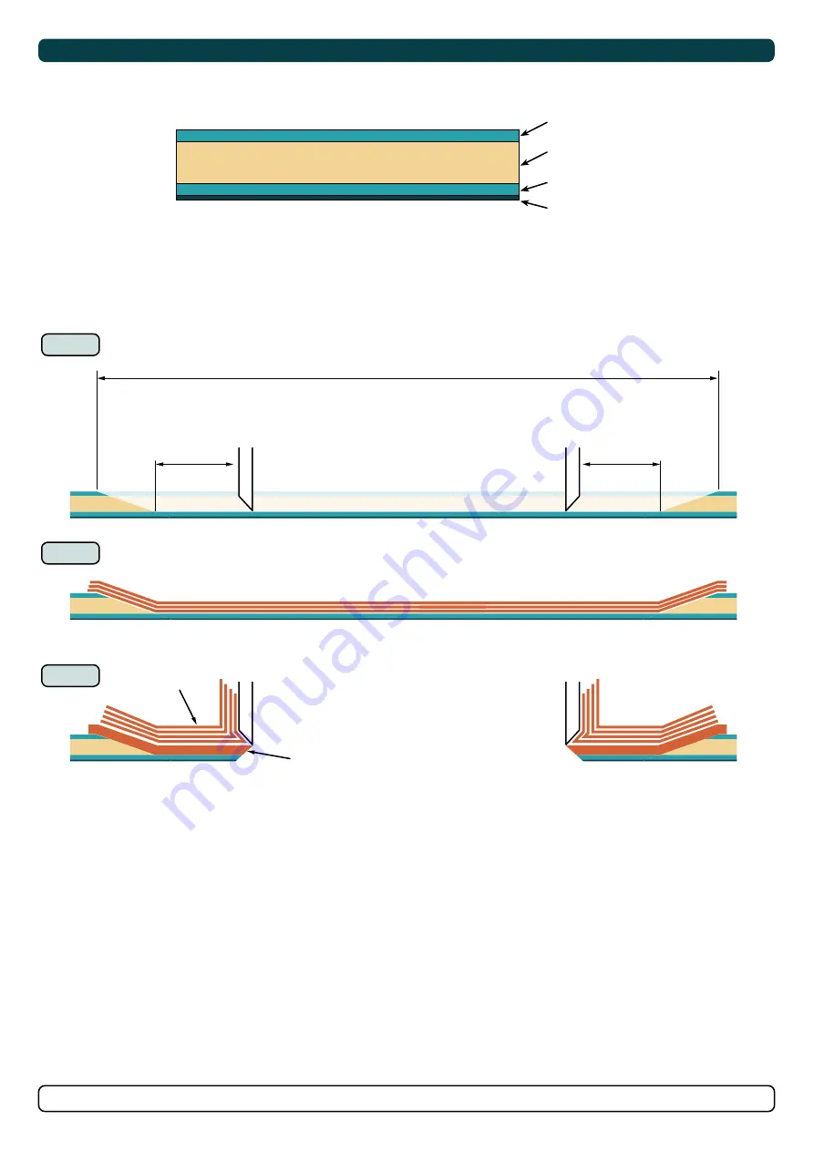
Preparing a Sandwich Hull for Retract Systems
MC_0067
Hull construction typical in many vessels is a composite layering method called a sandwich. To ensure the retract thruster is installed securely to these
hull types, additional hull structure reinforcement is required to strengthen the area around the Sleipner retract housing mould.
1. To achieve maximum strength and bonding in the area around the installation of the retract thruster remove the inner and core material to expose
the outer laminate. Remove enough area for a 100mm (minimum) clearance surrounding the retract thruster housing.
2. Reinforce the area with bonding to strengthen the hull for the operation of the retract thruster.
3. During the process of attaching the retract thruster housing build this area up to ensure enough strength of the hull.
(NB: Consult an experienced boat builder)
Cross section of a sandwich core hull
Inner laminate
Core
Outer laminate
Gel coat
MG_0472
1
2
3
Area removed to the outer laminate
Minimum 100mm space
surrounding the SR
thruster housing from the
removed core material.
SR thruster mould
SR thruster mould
Minimum 100mm space
surrounding the SR
thruster housing from the
removed core material.
SR thruster housing
Reinforced bonding from
step 2
Reinforced bonding
Extra bonding when
attaching the retract
housing to the hull


