background image

 15

7241

5

2022

-

ERV130 & ERV170 & ERV210

MG_0587

Bolt tightening force (4x)

33 Nm (24 lb/ft)

Install the relevant motor and 

other electronics according to 

electrical instructions in the 

manual

Motor to House Installation

1.  Install the motor onto the motor bracket ensuring the couplings and the drive shafts have locked together. The motor must be installed with 

the solenoid facing the control box. 

(NB: depending on your coupling you may need to wiggle the motor into place. Ensure the couplings are 

engaging correctly. Ensure the motor cable terminals are accessible for electrical installation later.)   

2.  Fasten the bolts holding the motor to the motor bracket with the above torque.

3.  Check the drive shafts engage by rotating the propeller. It is required the propeller can rotate via hand power.

 (NB: Rotating the propellers can be 

hard because of the gear reduction and the motor.)


4.  Apply the gear leg and propeller with anti-fouling designed for propellers. Do not apply to the propeller drive shaft, the anodes or the end of the 

gear leg facing the propellers.


(NB: The motor must be covered to avoid dust from fabrication/ maintenance operation entering the motor or the solenoids. After fabrication 

maintenance operations have ceased the cover must be removed before operating the thruster.)


MC_0068

!

 Please refer to the graphic for special considerations relating to your model 

!

MC_0143

Electrical Installation

WARNING 

Check the following with the main switch is set to off :

After all electrical connections have been completed check with an ohm meter that there is no electrical connection between 

1. electro-motor flange and the positive terminal on the motor 

2. electro-motor flange and the battery negative terminal on the motor 

If unsure contact skilled personnel.

1.  Information of electrical table. 

see next page

- All power cable lengths represent the total length of the combined (+) and (-) cables.

- Battery capacity is stated as minimum cold crank capacity, (CCA).

- Use slow blow rated fuses to hold stated Amp-Draw for min. 5 minutes.


- Consider the AMP hours (Ah) for your specifi c duty cycle. 

2.  Use appropriate sized cables and batteries with high cranking capacity to feed the thruster. The actual voltage at the motor while running the 

thruster decides the motors output RPM and thrust. Use larger cables and stronger batteries for better results.

- See electrical specifi cations for advised minimum cables and batteries (CCA).

3.  Install the main switch as close to the battery as possible and ensure the main positive lead can take loads without noticeable voltage drop. 


- Ensure the main switch (battery isolator) can be turned off independently and manually when not on board or in emergencies. 

- Ensure it is easily accessible and update instructions that this should be turned off like the boat’s other main switches.


It is advised to install a fuse in the positive lead for protection against short-circuiting. 

        - Ensure a slow type and appropriately sized to take the amperage draw for at least 5 minutes.

(NB: For Ignition Protected installations remember to use ignition protected fuses and switches if fi tted in areas that require this feature. 

Ensure to follow your national regulations)

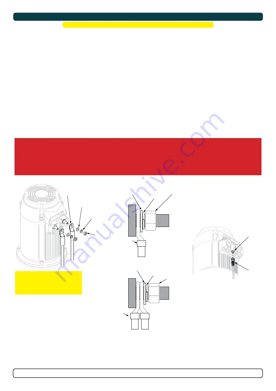
5.  Cable lugs must have adequate electrical and mechanical isolation and fi tted with cable lug covers.

6.  Fasten cables to the required torque. 

!

 Please refer to the graphic for special considerations relating to your model 

!

MG_0523

End nut

End nut

S-Link cable 

S-Link 

Connector

(M10) Nut

Tighten to *max 

13 Nm  (9.59 lb/ft)

Spring 

washer

Spring 

washer

Washer

Washer

Lugs

Lug

IMPORTANT

Do NOT use washers between lugs, 

this causes overheating and fire. Spring 

washers must be placed in the outer 

position before tightening the nut.

Lugs

End nut

Spring 

washer

Washer

Multi-lug 

configuration

Ensure lug faces 

are back to back.

Single-lug 

configuration

Ensure lug faces 

are back to back.

Содержание ERV130

Страница 1: ...TOR AS P O Box 519 N 1612 Fredrikstad Norway www sleipnergroup com DOCUMENT ID REVISION DATE LANGUAGE Installation Guide For E vision Electric Retractable Thruster Models ERV130 ERV170 ERV210 EN I M 7...

Страница 2: ...Product Measurements 4 Product Specifications 5 Positioning of the Retract thruster 6 Preparing a Sandwich Hull for Retract Systems 7 Marking and Trimming of SRF Flange 8 Installation Pre check 9 Requ...

Страница 3: ...one original Sleipner control panel to enable efficient troubleshooting if necessary MC_0105 MC_0425 For thruster systems Do not install the thruster in a position where you need to cut a stiffener s...

Страница 4: ...390 15 35 389 15 31 392 15 47 392 15 47 MH SRF flange height 98 3 85 98 3 85 98 3 85 98 3 85 98 3 85 98 3 85 RD Retracted hatch supplementary measurement 371 14 6 371 14 60 371 14 60 371 14 60 355 13...

Страница 5: ...lbs 21V 6 5 kW 8 7 hp TBA Sleipner eVision thrusters have Industry Leading Runtime at 100 thrust after that power may reduce to extend runtime if needed ERV130 48V 42V 62V 130 kg 284 lbs 42V 6 5 kW 8...

Страница 6: ...st not conflict with any other component of the vessel such as stern drives propellers trim tabs or rudders Therefore stern installations do not require to be installed on the hulls keel centre line a...

Страница 7: ...arance surrounding the retract thruster housing 2 Reinforce the area with bonding to strengthen the hull for the operation of the retract thruster 3 During the process of attaching the retract thruste...

Страница 8: ...thruster considering space required for installation operation and future maintenance 2 Mark the keel centre line on the inside of the hull Flip the SRF flange upside down and use the internal surfac...

Страница 9: ...chment is for temporary checking of thruster operation only 2 Temporarily connect 12 or 24 DC cables refer to the label on actuators for correct voltage to the 6 mm cables on the terminals on the cont...

Страница 10: ...keep the thruster stable 3 Open and close the hatch multiple times to ensure Clearance between the hull and hatch when the thruster is open Hatch closes flush with the hull and extra force is transfer...

Страница 11: ...d fibreglass cutting or similar which laminating material is the actual boat builders responsibility Cover the upper part if grinding is necessary After moulding material have cured run the retract me...

Страница 12: ...and thruster case materials 2 Place the upper thruster Housing down on the SRF flange 3 Insert and fasten bolts Start with the 4 corner bolts followed by the remaining to required torque MC_0068 Plea...

Страница 13: ...off excessive material before coating the hatch 9 Apply filler on to tunnel rings contact surface so the hatch will be secured properly Now re install hatch in its correct position Tighten bolts so h...

Страница 14: ...tion later 2 Fasten the bolts holding the motor to the motor bracket with the above torque 3 Check the drive shafts engage by rotating the propeller It is required the propeller can rotate via hand po...

Страница 15: ...e main positive lead can take loads without noticeable voltage drop Ensure the main switch battery isolator can be turned off independently and manually when not on board or in emergencies Ensure it i...

Страница 16: ...x 70 2 x 95 2 x 95 2 x 120 AWG 2 0 2 0 12 0 3 0 3 0 4 0 4 0 2 x 2 0 2 x 2 0 2 x 3 0 2 x 3 0 2 x 4 0 48V 290 A DIN 560 SAE 1330 EN 940 ANL 250 mm 70 70 70 95 95 120 120 2 x 70 2 x 70 2 x 95 2 x 95 2 x...

Страница 17: ...k Spur cable Control panel Wiring Diagram 24V Retract Thruster 12V BATTERY 12V BATTERY Fuse 5A Fuse 30A Fuse 30A Fuse 10A The below represents the wiring setup using a dual thruster system with a bow...

Страница 18: ...erminal polarity must be observed and connected correctly IMPORTANT AMS must be supplied with 24V only Use AMS serial 0 017664 or higher S Link Spur cable S Link Spur cable S Link Backbone cable S Lin...

Страница 19: ...d wire connected to 12VDC or 24VDC To reduce the risk of interference avoid routing the S Link cables close to equipment such as radio transmitters antennas or high voltage cables The backbone must be...

Страница 20: ...tuator s No 1 set to OFF when the retract has two actuators No 1 set to ON when the retract only has one actuator No 2 set to OFF when the retract does not have P8 type actuator s No 2 set to ON when...

Страница 21: ...Control Panel installation please refer to the Installation Guide accompanying the control panel to be installed MC_0398 Control Panel SLEIPNER MOTOR AS P O Box 519 N 1612 Fredrikstad Norway www sleip...

Страница 22: ...ear house and propeller but NOT anodes sealing rubber fittings or propeller shafts Propeller is fastened correctly to the shaft Propeller turns freely in tunnel The anode and or holding screw is tight...

Страница 23: ...tances of the defect to the best of the Claimant s knowledge including product identification and serial nbr the date and place of purchase and the name and address of the installer Proof of purchase...

Страница 24: ...250TC 48V E300 300TC 48V ERV300 300TC 48V Subject to installation maintenance and use conforming to their intended purpose is in conformity with the provisions of the following EU Directives Electrom...

Страница 25: ...48V ERV210 250TC 48V E300 300TC 48V ERV300 300TC 48V Subject to installation maintenance and use conforming to their intended purpose is in conformity with the provisions of the following UK Regulatio...

Страница 26: ...26 7241 5 2022 ERV130 ERV170 ERV210 MC_0037 Notes...

Страница 27: ...27 7241 5 2022 ERV130 ERV170 ERV210 MC_0037 Notes...

Страница 28: ...curacies or omissions it may contain Continuous product improvement may change the product specifications without notice Therefore Sleipner Group cannot accept liability for any possible differences b...

Отзывы: