background image

14 

SKYBLADE FANS - 

Where Form Follows Function

mOUNTING Method 2: Angle Irons

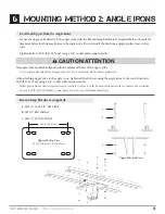
6.4b Fasten Double Angle Irons to Roof Structure Mounting Points:

ATTENTION: 

Do not tighten the hardware until the upper yoke has been mounted to the angle irons.

Grade 5 Hardware (customer supplied):

a.

 (4) 1/2”-13 GR 5 Bolt

b.

 (8) 1/2” Flat Washer

c. 

(4) 2-1/2” Square Washer (see diagram)

d.

 (4) 1/2” Nylock Nut

Do not install the fan from a single purlin, truss, or bar joist.

Ne pas installer le ventilateur à partir d’une même purlin, botte, ou solives.

The angle irons must be fastened to the roof structure at each end.

Les cornières doivent être attachés à la structure de toit à chaque extrémité.

Fasten the angle irons to the roof structure mounting points at each end with customer-supplied Grade 5 hardware 

as shown.

Fixer les cornières aux points de fixation de la structure du toit à chaque extrémité fourni par le client 5 e année du 

matériel comme indiqué.

CAUTION/ATTENTION

!

Содержание STOL Series

Страница 1: ...Follo FollowsFunctionWhereFormFollowsFunctionW FunctionWhereFormFollowsFunctionWhereFo WhereFormFollowsFunctionWhereFormFollo FollowsFunctionWhereFormFollowsFunctionW FunctionWhereFormFollowsFunctionWhereFo WhereFormFollowsFunctionWhereFormFollo FollowsFunctionWhereFormFollowsFunctionW FunctionWhereFormFollowsFunctionWhereFo WhereFormFollowsFunctionWhereFormFollo FollowsFunctionWhereFormFollowsFun...

Страница 2: ...ce with all applicable codes and standards including fire rated construction Failure to comply could result in personal injury electric shock death fire and or property damage Before attempting installation servicing or cleaning unit switch power off at the service panel and lock the service disconnecting means to prevent power from being switched on accidentally Pour réduire le risque d incendie ...

Страница 3: ...r purposes other than those intended by the manufacturer L installation de ce ventilateur nécessite l utilisation d outils électriques Suivez les consignes de sécurité figurant dans le manuel du propriétaire de ces outils et ne pas les utiliser à des fins autres que celles prévues par le fabricant This unit has an unguarded impeller Do not use in locations readily accessible to people or animals C...

Страница 4: ... and SkyBlade Fans are the trademarks of Skyblade Fans STOL Airfoils patent pending STOL Control and Power Assembly patent pending Model Description Length Y Width X Height Z Shipping Weight STOL Control Airfoil Assembly 33 0 839mm 30 5 775mm 30 5 775mm 145 lbs 65 kg Model Description Width X Length Y Height Z Shipping Weight 1236 6 12 3 6M Fan 5 6 1680mm 24 0 610mm 17 0 432mm 125 lbs 57 kg 1443 6...

Страница 5: ...issing kit contents prior to installing unit Wingtip Fence x6 Airfoil x6 VFD Enclosure x1 Strain Relief Bushing x3 Control Box x1 Strain Relief Bushing x1 Motor Chassis x1 Upper Yoke x1 Lower Yoke x2 Clamping Plate x2 Control Wire x1 100 Motor Supply Cable x1 x 25 6 6 x 5 8 Flat Phil Screw 4 1 2 13x2 1 2 GR 5 Bolt 4 1 2 13x3 1 2 GR 5 Bolt 4 1 2 13x1 1 2 GR 5 Bolt 24 1 2 Flat Washer 12 1 2 13 Nyloc...

Страница 6: ...rating height D Lower Yoke Connects the chassis to mounting assembly E Chassis Housing for the motor and gear reducer F Airfoil Provides air movement G Wingtip Fence Improves air movement efficiency by reducing drag Series STOL STOL STOL STOL STOL STOL Diameter 12 3 6M 14 4 3M 16 4 9M 18 5 5M 20 6 1M 24 7 3M Blades 6 6 6 6 6 6 Voltage Input 115230460575115230460575115230460575115230460575115230460...

Страница 7: ...nsion bars and smaller fans are available from Skyblade Fans 2 3 Fire Suppression Systems and Fan Placement If installing Fans in a location where fire sprinklers are in place do not interfere with their correct operation Fans should be located in the center of each sprinkler quadrant and no less than 3 feet below the sprinkler Review all codes applicable to sprinkler systems prior to installation...

Страница 8: ... seconds The event of this max torque being applied is unlikely and will only apply due to a failure of the variable frequency drive and its soft start technology 3 4 Safety Cable A Skyblade fan should never be run without proper installation of Safety Cables These are supplied with every fan You must install safety cable for warranty to be in effect 3 5 Guy Wires While in operation a fan can sway...

Страница 9: ...e equipment The spacing between multiple fans should be no less than 2 5x the fans diameter when measured from the center of the fans The mounting structure must be able to withstand the torque which is generated by the fan A 20 diameter fan generates a maximum of nearly 300 ft lb 406 7 N m of torque during operation 4 2 Electrical Installation To reduce the risk of electrical shock wiring should ...

Страница 10: ...tallez les cales de serrage que si l épaisseur de la semelle de la poutre supérieure à 3 8 1 cm Les trous de fixation de la cale sont plus près d un côté que de l autre Assurez vous que ce côté est confronté à la poutre CAUTION ATTENTION Support Directly From Building Structure All mounting instructions assume that the building structure from which the fan will be hung is of sound construction und...

Страница 11: ...la plaque de serrage ou des cales de serrage lors du montage du ventilateur à cornières Beam clamps are only intended for I beam installations Serre poutres sont uniquement destinées aux installations de faisceaux WARNING AVERTISSEMENT Do not install the fan from a single purlin truss or bar joist Ne pas installer le ventilateur à partir d une seule panne botte ou solives Unsupported angle iron sp...

Страница 12: ...sten Angle Irons Together if span is longer than 8 If the angle iron span is 8 2 4m or less proceed to step 6 4a on the following page If the angle iron span is longer than 8 2 4m it is necessary to use double angle irons Locate the center of the angle iron length Drill 9 16 1 4cm diameter hole through the center of the vertical wall of the angle iron Drilling through a total of four angle irons P...

Страница 13: ...re Washer see diagram d 4 1 2 Nylock Nut Do not install the fan from a single purlin truss or bar joist Ne pas installer le ventilateur à partir d une même purlin botte ou solives The angle irons must be fastened to the roof structure at each end Les cornières doivent être attachés à la structure de toit à chaque extrémité Fasten the angle irons to the roof structure mounting points at each end wi...

Страница 14: ...t Do not install the fan from a single purlin truss or bar joist Ne pas installer le ventilateur à partir d une même purlin botte ou solives The angle irons must be fastened to the roof structure at each end Les cornières doivent être attachés à la structure de toit à chaque extrémité Fasten the angle irons to the roof structure mounting points at each end with customer supplied Grade 5 hardware a...

Страница 15: ...2 Flat Washer c 4 1 2 13 Nylock Nut 11 1 4 28 32cm Upper Yoke Top View 13 3 4 34 9cm x 8 20 32cm a b b c Upper Yoke Side View The angle irons should be aligned with the outermost holes of the upper yoke Les cornières devraient être alignées avec les trous extérieurs de la culasse supérieur After attaching upper yoke to the angle irons tighten all the bolts securing the angle irons to the roof stru...

Страница 16: ... should be placed on both sides of the plate for each bolt 6 9 Pre Drill Angle Iron Brackets Holes Your angle iron should be cut to allow 1 2 1 27 cm clearance between the end of the angle iron and the purlin you are mounting to Drill one 9 16 1 4 cm diameter hole centered vertically exactly 1 2 54 cm from the edge on both ends of the vertical wall of the angle iron Drill a second hole exactly 3 7...

Страница 17: ...d secured to the outside faces of the purlin brackets 6 12 Attach Upper Yoke to Angle Iron Attach the upper yolk to the angle irons using the provided 1 2 grade 5 bolts washers and nylock nuts See section 6 5 Attach Upper Yoke to Angle Iron to continue installation Purlin Bracket Hardware per set supplied a 2 1 4 Formed Steel Purlin Bracket b 2 1 4 Steel Purlin Backplate c 16 1 2 13 1 3 4 GR 5 Bol...

Страница 18: ...the fan and building or even personal harm Skyblade Fan Company is NOT liable for any damages or injury resulting from improper installation Calculs de masse doit être fait pour sélectionner le unistrut de taille appropriée Défaut de le faire peut aboutir à dommages au ventilateur et de bâtiment ou même un préjudice personnel Skyblade Fan Company est pas responsable de tout dommage ou blessure rés...

Страница 19: ... the C Channels with open sides facing away from each other onto threaded rods using 1 2 washers and 1 2 13 nylock nuts thus sandwiching the top chord of the joist Torque to 90 ft lbs 6 Route safety cable through a whole drilled in the beam assembly and above the top chord of the joist at each mounting point Secure safety cable using two wire rope clips on each end of the cable 7 Continue with fan...

Страница 20: ...ngle Pivot Hardware supplied a 2 1 2 13 x 3 1 2 GR 5 Bolt b 4 1 2 Flat Washer c 2 1 2 13 Nylock Nut 7 2 Secure Upper Safety Cable Secure the safety cable to the I beam or angle iron by wrapping the safety cable around it threading the cable through the 17 32 open hole on the top of the extension tube and securing the ends with the gripple fastener as shown The cable must have as little slack as po...

Страница 21: ... 5 Bolt b 4 1 2 Flat Washer c 2 1 2 13 Nylock Nut 7 4 Attach Motor Frame to lower yoke Attach the motor frame to the lower yoke with the Motor Hub Hardware as shown Tighten bolts to 90 ft lbs 122 N m using a 3 4 socket with torque wrench Motor Chassis Hardware supplied a 4 1 2 13x1 1 2 GR 5 Bolt b 8 1 2 Flat Washer c 4 1 2 13 Nylock Nut c b a a b c The Motor Frame is heavy use a minimum of two per...

Страница 22: ...eference Eye Hook illustration on page 21 1 Slide the unlooped end of the guy wire through the eye hook 2 Feed the wire through the loop on the other end of the wire 3 Pull tight so the wire tightens on the eye hook Attach each guy wire to each loop on the lower section of the chassis 1 Slide the gripple fastener as supplied over the opposite end of the wire 2 Feed the end of the guy wire through ...

Страница 23: ...ple clamp Eye Hook a Beam Clamp b Eye Hook c Gripple Wire Loop Gripple Maximum Angle Gripple Ceiling Beam 45 Maximum Guy Wire a b c Make certain all electrical cords are not obstructed by guy wires Assurez vous que tous les câbles électriques ne soient pas obstruées par des haubans WARNING AVERTISSEMENT a Chassis Eye Hook b Guy Wire c Gripple Fastener a b c ...

Страница 24: ... remove hex plug from gearbox a Apply pipe dope or thread tape to reducer b and insert into gearbox a using 5 8 wrench Using a 7 16 wrench insert valve c into reducer b Failure to install pressure release valve will void manufacturer warranty Pressure Release Valve Hardware supplied a Gearbox b Reducer c Pressure release valve c b a ...

Страница 25: ...the risk of personal injury do not bend the blade brackets when installing the brackets balancing the blades or cleaning the fan Do not insert foreign objects in between rotating fan blades Pour réduire le risque de blessure ne pas plier les crochets lame lors de l installation les crochets l équilibre entre les lames ou de nettoyer la ventilateur Ne pas insérer d objets étrangers entre les pales ...

Страница 26: ...26 SKYBLADE FANS Where Form Follows Function Slide airfoil onto struts until airfoil holes and strut holes are aligned 9 installing Airfoils 9 1a Attach Airfoils to Hub ...

Страница 27: ...lling Airfoils 9 1b Attach Airfoils to Hub NOTE Fan turns in counter clockwise rotation when looking up NOTE Forward position on control blows air downward Airflow Low Pressure High Pressure Counter clockwise rotation of blade Trailing Leading Top Bottom ...

Страница 28: ... wrench Second tighten the bolts along the inside to 29 ft lb 39 N m using a 1 2 socket with torque wrench Boomerang Bracket Kit supplied a 6 5 16 18x2 GR 5 Bolt b 6 5 16 18x1 3 4 GR 5 Bolt c 24 5 16 Flat Washer d 12 5 16 18 Nylock Nut WARNING AVERTISSEMENT Disconnect power to the motor before installing the airfoils Débranchez l alimentation du du moteur avant d installer les profils aérodynamiqu...

Страница 29: ...securely attached to the strut Using a Phillips head screwdriver fasten wingtip to airfoil using a 6 x 5 8 Flat Phil Screw Wingtip Hardware Kit supplied a 6 6 x 5 8 Flat Phil Screw IMPORTANT After installation is complete replace plug on gear reducer elbow with pressure release valve provided by SkyBlade Fan Company Wingtip Wingtip Airfoil Screw ...

Страница 30: ...tic bushing on the motor cover and on the motor electrical box 5 Finish wiring the motor cable to the motor screw on the motor electrical box cover and tighten the bushings 6 Align the slots on the motor cover to the sockets in the chassis 7 Screw in the motor cover thumb screws and tighten with a 3 16 allen wrench 8 On the non electrical side orient the cover so that the three ventilation slots a...

Страница 31: ...t and are not included standard 9 5 Hub Cover Assembly 1 Align the hub cover with the threaded hole on the reducer output shaft 2 Screw in the provided hub cover bolt with the washer and tighten with a 9 16 wrench Hub Cover Hardware supplied a 1 3 8 24x3 4 Hex Cap Bolt b 1 3 8 Flat Washer Chassis Assembly Hub Cover Hub Cover Bolt Hub Cover Washer ...

Страница 32: ...g of panel and fan per the NEC is required for safety and proper operation 3 Remote switch remote cable motor cable and motor cable glands supplied by Skyblade Fans 4 Length of cable from drive to motor to be 25 feet or less 5 Length of cable from controller to switch box to be 100 feet or less 6 VFD cable must be ran in conduit or raceway per NEC Câble VFD doit être exécuté dans un conduit ou che...

Страница 33: ...ontinue to hold a charge after removal of its main supply Before working on the fan controller ensure isolation of mains supply from line inputs at the fan controllers disconnect L1 L2 L3 Wait three 3 minutes for capacitors to discharge to safe voltage levels Darkened display LEDs are NOT an indication of safe voltage levels Failure to do so many result in personal injury or death Les contrôleurs ...

Страница 34: ...ens lorsque vous alimentez le ventilateur Ne pas brancher le ventilateur à une source d alimentation endommagé ou dangereux Ne pas tenter de résoudre les dysfonctionnements électriques ou des échecs sur votre propre Contactez Skyblade fans au 1 586 806 5107 si vous avez des questions concernant l installation électrique de ce ventilateur For use with manufacturer supplied variable frequency drive ...

Страница 35: ...SKYBLADE FANS Where Form Follows Function 35 10 Electrical Installation VS1ST 1 Phase 115V 230V Wiring Diagram VS1ST 3 Phase 230V 460V 575V Wiring Diagram ...

Страница 36: ...36 SKYBLADE FANS Where Form Follows Function 10 Electrical Installation ACS250 1 Phase 115V Wiring Diagram ACS310 1 Phase 230V Wiring Diagram ...

Страница 37: ...SKYBLADE FANS Where Form Follows Function 37 10 Electrical Installation ACS310 3 Phase 230V 460V Wiring Diagram ACS250 3 Phase 575V Wiring Diagram ...

Страница 38: ... cable and twist the shield under the grounding clamp Connect the phase conductors to the U2 V2 and W2 terminals Use a tightening torque of 0 8 Nm 7 lbf in for frame sizes R0 R2 1 7 Nm 15lbf in for R3 and 2 5 Nm 22 lbf in for R4 2 Secure the cables outside the drive mechanically 1 2 2 Job Site Installed Factory Installed ...

Страница 39: ...o not run your controller and sensitive equipment on the same power line c Install properly sized EM RFI filter d Contact Customer Service at 1 586 806 5107 5 Error code appears on VFDs digital interface Please contact Skyblade Fans customer service to resolve issue WARNING AVERTISSEMENT Electrical Shock Hazard RISQUE D ÉLECTROCUTION Risk of fire electric shock or injury to persons during cleaning...

Страница 40: ...Débranchez l appareil de l alimentation électrique et laisser suffisamment de temps pour la décharge électrique avant l entretien Before servicing or cleaning unit switch power off at the service panel and lock the service disconnecting means to prevent power from being switched on accidentally Avant de réparer ou de nettoyer l appareil coupez l alimentation électrique au panneau de service et blo...

Страница 41: ...airfoils are secured to one another by boomerang brackets 6 Ensure screws securing wingtip fences to airfoils are tight 7 Check to see if gear reducer is leaking if so please contact customer service at 1 586 806 5107 8 Check for the presence of the safety cable and wire rope clips The cable should be wrapped around the I beam or angle irons leaving as little slack as possible The wire rope clips ...

Страница 42: ...42 SKYBLADE FANS Where Form Follows Function 13 Replacement Parts Replacement Part List If you have any questions please contact customer service at 1 586 806 5107 Part No Description ...

Страница 43: ...SKYBLADE FANS Where Form Follows Function 43 Notes ...

Страница 44: ...24501 Hoover Road Warren MI 48089 USA Telephone 1 586 806 5107 Fax 1 586 806 5109 E Mail sales skybladefans om www SKYBLADEFANS com LIM STOL 0416 ...

Отзывы: