


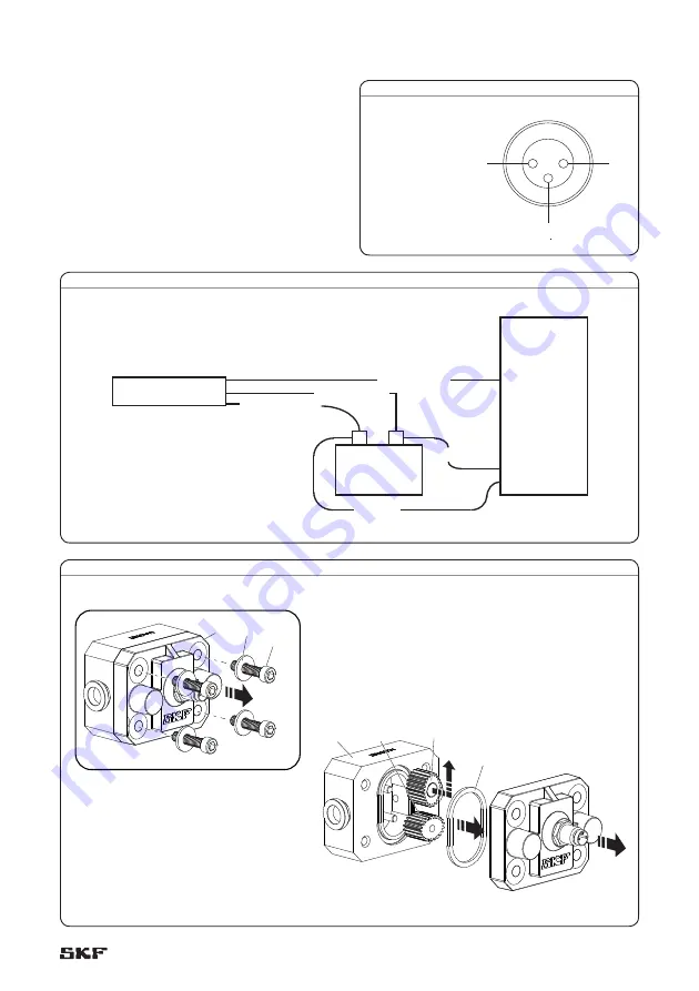
V DC (brown)
+ V DC
Signal (black)
Ground (blue)
Ground blue
+V DC
PLC or
controller
Digital
Input
DC power
source
Flow sensor cable
Ground
Fig. 3
Fig. 2
1.4
2.3
2.1
2.4
1.2
1.3
1.1
Detector disassembly
1
Remove head bolts (
2.4
) and washers (
2.3
)
from cover (
2.1
) (
† fig. 3
).
2
Remove the detector cover (
2.1
) and
o-ring (
1.4
).
3
Remove oval gears (
1.2, 1.3
).
4
Clean and inspect all parts. Replace any
suspect, worn or damaged components.
Wire pin connections
1
Ground
2
Output signal
3
Positive V DC
1
2
3
Fig. 1
5


