background image

チコーエアーテック株式会社

Copyright CHIKO AIRTEC CO., LTD. 2009

16

6.3

2次(メイン)フィルタの交換

Replacement of secondary filter

6.4

排気

HEPA

フィルタ交換について(

SKV-450AT-ACC-V1

チューブ(ニップル)を取 り外 さずに緩 めた状 態 で、ノブだけを取 り外 して、フィルタを交
換 することも可 能 です。この場 合 、ノブを廻 す時 にチューブが廻 って 引 っ張 られることが

ありますので、ご注 意 下 さい。また、ニップルを取 り外 した場 合 には、

ニップルを垂 直

取 り付 けてください。斜 めに差 し込 むと目 詰 まりランプの誤 作 動 の原 因 となります。

You can replace the secondary filter by removing only the knob without removing the tube (nipple) (but
loosening the tube (nipple)).In this case, note that the tube may be turned and pulled when the knob is turned.
After removing the nipple, make sure to

attach it vertically

. If the nipple is inserted diagonally, the

clogging indicator lamp may malfunction and turn ON

1.

フィルタケースのパッチン錠を外し、1次フィルタ(フィルタバッグ)を取りはずしておきます。

Release the snap locks of the filter case, and remove the primary filter (filter
bag).

2.

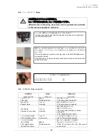
チューブが廻らないようにニップルを押さえながら、マイナスドライバーで左に廻して外し
ます。

While pressing the nipple to prevent turning of the tube, turn the nipple
counterclockwise with a slotted screwdriver to remove it.

3. ノブを左に廻して、取り外し、ワッシャーも取り外します。

Turn counterclockwise the knob to remove it, and then remove the washer also.

4. 円筒フィルタを手前に引きながら、ゆっくり取り外して下さい。

While pulling forward the cylindrical filter, slowly remove it.

ノブ

Knob

ニップル

Nipple

取り付け時は、垂直に!!

Attach the nipple vertically!

①活性炭室を外してください。
本体を横向きに倒して下さ
い。

活性炭室

本体底面 (キャスター台)

②キャスター横の

M6

ビスを外

してください。キャスター台を外
して下さい

HEPA

フィルタを取り出し、交

換して下さい。

Содержание SKV-250AT-ACC

Страница 1: ...is instruction manual thoroughly and handle this SK Series machine correctly so that you can use it safely for a long time and enjoy its full performance Symbols used in this manual WARNING This symbo...

Страница 2: ...osene paint etc Explosive dust Aluminum magnesium titanium zinc epoxy etc Dust containing sparks Dust containing sparks generated by high speed cutters grinders welding machines etc Fire sources Cigar...

Страница 3: ...T AT panel 7 4 3 Remote connector 9 4 4 Confirmation before operation 9 4 5 Operation procedure 10 5 Remote Cable Sold Separately 11 5 1 Electrical circuit diagram 11 5 2 Remote Cable 11 5 3 Color and...

Страница 4: ...y Do not install it outdoors 0 40 80 Install the product in a place without dew condensation at room temperature ambient temperature 0 to 40 C humidity 80 or less High temperature and dew condensation...

Страница 5: ...repair 1 6 Disposal Dispose of the product properly as industrial waste 2 Confirmation and Preparation at Arrival After unpacking make sure that all parts are provided Contact our company immediately...

Страница 6: ...e 1 Active carbon Colliding with granulated active carbon collects the particles passed through the primary filter and odor is removed carbon particle into the blower Main filter Collecting Adsorbing...

Страница 7: ...When the filter replacement indicator lamp red turns ON replace the primary filter filter bag If the filter replacement indicator lamp does not turn OFF even after replacement of the primary filter f...

Страница 8: ...eases by 1 level Minimum suction level Approximately 60 Hi 1 1 100 Hi switch Every time this switch is pressed the performance increases by 1 level Maximum suction level 100 ON switch and OFF switch t...

Страница 9: ...ng plug are connected correctly insulation is provided properly and the rated voltage is realized Confirm items 1 to 3 above and then proceed to the item 4 AT Turn ON the MAIN POWER switch and confirm...

Страница 10: ...nd confirm that the power indicator lamp lights Starts the dust collector AT ON Press the ON switch to start the operation 7 Choose operation ability in seven levels Push Lo switch or Hi switch in AT...

Страница 11: ...panel and cause The wire 7 yellow is put inside a shrinkable tube so that it cannot be short circuited with other wires Remote operation switch ON Shifting to remote mode Remote control is possible in...

Страница 12: ...ion The AT panel is disabled while the wires 4 and 8 are short circuited Yellow white Black White Operation pressure signal Output signals Transfers the current operation output Analog signal 0 5V Imp...

Страница 13: ...Copyright CHIKO AIRTEC CO LTD 2009 13...

Страница 14: ...in body Transfer required output signals in accordance with the explanation in 5 3 Color and signal of each wire AT ON Lo Hi Change with Lo Hi switch pushing the ON switch of main body AT panel when y...

Страница 15: ...fore starting inspection Using a worn or damaged filter will release sucked dust to the atmosphere and damage electrical parts Make sure to inspect and maintain to prevent failures and accidents in th...

Страница 16: ...make sure to attach it vertically If the nipple is inserted diagonally the clogging indicator lamp may malfunction and turn ON 1 Release the snap locks of the filter case and remove the primary filter...

Страница 17: ...ds generated Is the installation level correct Filter installation status Once month Are the filters installed securely Filter clogged status Suction force check During operation Does the suction hose...

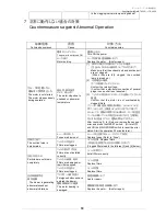
Страница 18: ...verheated by clogged filters 3 30 After checking 1 to 3 above remove the cause of error and press the RESET switch Or turn OFF and ON the MAIN POWER switch to reset the error status Start the operatio...

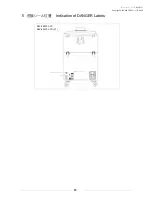
Страница 19: ...Copyright CHIKO AIRTEC CO LTD 2009 19 8 Indication of DANGER Labels SKV 250AT ACC SKV 450AT ACC V1...

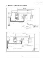
Страница 20: ...Copyright CHIKO AIRTEC CO LTD 2009 20 9 Electrical Circuit Diagram SKV 250AT ACC SKV 450AT ACC V1...

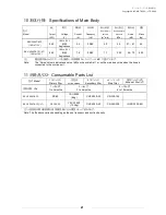
Страница 21: ...7 2 35 58 70 62 5 1 dB Note The Noise column indicates a value dB on the scale A at 1 m on the main body side when the hose is connected to the suction port 11 Consumable Parts List Model 1 Primary f...

Страница 22: ...ubject to change without prior notice Memo about purchase Model Manufacturer s serial number Date of purchase Start of operation Your name Address Phone Person in charge LTD 562 0012 1 1 33 1 1 33 Hak...

Отзывы: