


チコーエアーテック株式会社
Copyright CHIKO AIRTEC CO., LTD. 2009
11
5
別売リモートケーブルについて
Remote Cable (Sold Separately)
5.1
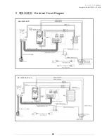
電気回路図
Electrical circuit diagram
インダクタ(リレー等を付加する場合はノイズリミッター
(約33Ω+0.1μF)又はダイオード
等を付けて下さい
LOAD
LOAD
1
4
2
3
5
6
8
7
LOAD
LOAD
LOAD
運転入力信号
遠隔操作切替信号
運転圧力信号
フィルタ目詰信号
運転信号
過負荷信号
サービス電源
GND
DC 1~5V
耐圧 DC 50V
100mmA以下
DC 12V
+側
5.2
ケーブル
Remote Cable
⑦(黄)は、他の線と短絡させないで下さい。
AT
パネルが損傷し、故障の
原因となります。
Do not short-circuit the wire [7] (yellow) with other wires.
Such short-circuit may damage the AT panel, and cause
⑦(黄)は、他の線と短絡しないよう収縮チュ
ーブの中に入っています。
The wire [7] (yellow) is put inside a shrinkable
tube so that it cannot be short-circuited with
other wires.
リモート運転
Remote operation switch
リモートモード移行
(ON 時に遠隔操作可能、この時パネル操作は不可)
Shifting to remote mode
(Remote control is possible in the ON, and the panel
is impossible to control at this time.)
②圧力アナログ信号
出力 ≧4.7kΩ
※温度補正なし
Pressure
analog output
:
Output impedance 4.7kΩ
Temperature correction is not provided.
参照例
Reference example
インダクター(リレー等)を付加する場合は出力端子
(端子番号 3.5.6)にノイズリミッター(約 33Ω+0.1μ
F)を付けて下さい
Attach a noise limiter (Approximately 33Ω+0.1μ
F) to the output terminals(Nos.1.2 and 3)
When adding inductors(such as relays)