background image

10

Schritt 3

Montieren Sie den Sattel (11) mit 3 Muttern (24) und 3 Unterlegscheiben (32) oben auf der Sattelstütze 
(03). Schieben Sie die Sattelstütze mit montiertem Sattel dann in den Hauptrahmen (01), richten Sie 
die Bohrungen zueinander aus und sichern Sie die Stütze mit dem Schnellversteller (13).
Die Sitzhöhe kann entsprechend Ihren persönlichen Bedürfnissen verstellt werden.

AUFBAUANLEITUNG

Содержание FOLDAWAY X-1000 PLUS

Страница 1: ......

Страница 2: ...em Gerät trainieren Die Kleidung muss so beschaffen sein dass diese nicht aufgrund Ihrer Form z B Länge während des Trainings irgendwo hängen bleiben kann Die Schuhe sollten passend zum Trainingsgerät gewählt werden grundsätzlich dem Fuß einen festen Halt geben und eine rutschfeste Sohle besitzen 7 Verwenden Sie das Gerät nur für den vorgesehenen Zweck Verwenden Sie keine Zusatz oder Ersatzteile d...

Страница 3: ...skandika com Scannen Sie den QR Code mit Ihrem Smartphone INHALTSVERZEICHNIS Inhaltsverzeichnis Sicherheitshinweise 2 Checkliste 4 Materialset Teileliste 4 Teileliste 5 Explosionszeichnung 6 Aufbauanleitung 8 Computerbedienung 15 Übungsanleitung 18 Garantiebedingungen 56 ...

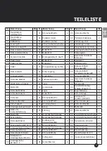
Страница 4: ...ichnung Menge Zeichnung 13 Schnellversteller 1 14 Schraube M8x60L 4 15 Welllscheibe φ8 3xφ22 6 16 Mutter M8 6 17 Schraube M8x50L 2 18 Schraube M8x45L 6 22 Unterlegscheibe φ8 3xφ25 2 24 Mutter M8 2 25 Federscheibe 4 26 Schraube M6x12L 2 27 Federscheibe GB T 93 6 2 28 Unterlegscheibe φ6 5xφ13 2 31 Schraube mit Unterlegscheibe M5x10L 2 33 Schraube M6x20L 2 94 Maulschlüssel S13 15 1 95 Innensechskants...

Страница 5: ... Welllscheibe φ8 3xφ22 6 47 Feder 1 79 Riemenrolle 1 16 Mutter M8 7 48 Andruckrolle 1 80 Kunststoff Unterleg scheibe φ14xφ10 3 1 17 Schraube M8x50L 2 49 Lager 2 81 Lagerhalterung 2 18 Schraube M8x45L 6 50 Mutter M10 2 82 EVA Unterlage 1 19 Computer 1 51 Schraube M8x15L 2 83 Endkappe für vorderen Standfuß 2 20 Hinterer Standfuß 1 52 Schraube M5x20L 1 84 Widerstandsregler 1 21 Sicherheitsstif 1 53 H...

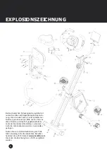
Страница 6: ...mmer gekennzeichnet Bitte nennen Sie uns diese Nummer um das Teil gegebenenfalls im Laufe der Garantiezeit kostenlos zu ersetzen Auch die Versandkosten werden von skandika getragen Nutzen Sie zur exakten Bestimmung der Teile falls notwendig bitte das kostenlose Benutzer handbuch im pdf Format auf www skandika com Hier kann die Zeichnung bis zu 500 vergrößert werden ...

Страница 7: ...7 DE EXPLOSIONSZEICHNUNG ...

Страница 8: ...Position durch Einstecken in die andere Bohrung Befestigen Sie dann den vor deren Standfuß 08 am Vorderteil des Hauptrahmens 01 mit 2 Schrauben 14 2 Wellscheiben 15 und 2 Muttern 16 Befestigen Sie den hinteren Standfuß 20 am hinteren Teil des Hauptrahmens 02 mit 2 Schrauben 14 2 Wellscheiben 15 und 2 Muttern 16 AUFBAUANLEITUNG ...

Страница 9: ...6 2 Federscheiben 27 2 Unterlegscheiben 28 und 2 Schrauben 33 Setzen Sie die Computerhalterung 29 in die Stütze für Computerhalterung 23 ein und fixieren Sie die Halterung mit den 2 Schrauben mit Unterlegscheibe 31 Verbinden Sie nun das Sensorkabe loberteil welches aus dem Computer 19 kommt mit dem Sensorkabel Mittelteil 30 AUFBAUANLEITUNG ...

Страница 10: ...f der Sattelstütze 03 Schieben Sie die Sattelstütze mit montiertem Sattel dann in den Hauptrahmen 01 richten Sie die Bohrungen zueinander aus und sichern Sie die Stütze mit dem Schnellversteller 13 Die Sitzhöhe kann entsprechend Ihren persönlichen Bedürfnissen verstellt werden AUFBAUANLEITUNG ...

Страница 11: ... Rückenpolster Halterung 06 mit je 2 Schrauben 17 Unterlegscheiben 22 und Muttern 24 an der Sattelstütze 03 Montieren Sie dann das Rückenpolster 12 mit 4 Schrauben 18 und 4 Federscheiben 25 an der Rückenpolster Strebe 07 AUFBAUANLEITUNG ...

Страница 12: ...12 Schritt 5 Befestigen Sie den hinteren Lenkergriff 05 mit je 2 Schrauben 18 Wellscheiben 15 und Muttern 16 an der Rückenpolster Halterung 06 AUFBAUANLEITUNG ...

Страница 13: ...13 DE Schritt 6 Bringen Sie den linken Pedalriemen am linken 09 markiert mit L und den rechten Pedalriemen am rechten Pedal 10 markiert mit R an AUFBAUANLEITUNG ...

Страница 14: ...rzeigersinn das linke Pedal 09 wird entsprechend am linken Pedalarm befestigt Schraubrichtung entgegen dem Uhrzeigersinn Die Pedale sind zur besseren Zuordnung mit R für rechts und L für links markiert AUFBAUANLEITUNG PRÜFEN SIE VOR DER BENUTZUNG OB ALLE SCHRAUBEN UND MUTTERN FESTGEZOGEN SIND ...

Страница 15: ...nnen Der Computer schaltet in den Standby Modus wenn für ca 4 Minuten kein Signal vom Trainingsgerät übermittelt wird Im Standby Modus ist keine Bluetooth Übertragung möglich Starten Sie ein Training Pedalbenutzung damit der Computer wieder in den normalen Trainingsmodus versetzt wird 2 Bedienungsanleitung App 2 1 Installationsvoraussetzungen 2 1 1 iOS Version 7 1 und neuer mit Bluetooth 4 0 Unter...

Страница 16: ...das Fahrrad Icon spinning und stellen Sie sicher dass der Trainingscomputer sich nicht im Standby Modus befindet Die automatische Verbindungssuche startet nach ca 5 sekündiger Phase ohne weitere Bedienung 2 4 Funktionswertanzeige in realer Zeit 2 4 1 Im Hauptanzeigefenster werden alle verfügbaren Trainingsdaten Zeit Tempo Distanz Gesamt Distanz Kalorienverbrauch Herzfrequenz Körperfett angezeigt D...

Страница 17: ...en hier angezeigt max 999 9 kcal PULSE Der Computer zeigt die theoretische Pulsfrequenz Schläge Min an Für eine korrekte Anzeige stellen Sie bitte sicher dass Sie die beiden Sensoren korrekt mit Ihren Handflächen umfassen Es kann u U bis zu 2 Minuten dauern bevor die Pulsfrequenz korrekt gemessen wird Anmerkungen a Der kleine Pfeil zeigt immer auf die gerade aktive Funktion auf dem Computergehäuse...

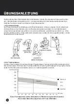
Страница 18: ... Jede Dehnung sollte für ca 30 Se kunden gehalten werden dabei sollte keine Gewalt oder zu starker Druck ausgeübt werden treten Schmerzen auf hören Sie auf 2 Die Trainingsphase In dieser Phase sollten Sie Leistung bringen Regelmäßiges Training wird Ihre Beinmuskulatur flexi bler werden lassen Während des Trainings sollten Sie in einem gleichmäßigen Tempo laufen Dabei sollte Ihre Herzfrequenz die Z...

Страница 19: ...uskeldefinition zu erreichen müssen Sie die Widerstandseinstellung relativ hoch einstel len Dies beansprucht Ihre Beinmuskulatur in stärkerem Maße das kann dazu führen dass Sie nicht so lange trainieren können wie gewünscht Wenn Sie jedoch auch Ihre Fitness trainieren möch ten müssen Sie Ihr Trainingsprogramm abwechslungsreicher gestalten Sie sollten normal während der Aufwärm und Abkühlphase trai...

Страница 20: ...ways wear appropriate workout clothing when exercising DO NOT wear robes or other clothing that could become caught in the machine Running or aerobic shoes are also required when using the machine 7 Use the machine only for its intended use as described in this manual DO NOT use attachments not recommended by the manufacturer 8 Do not place any sharp objects around the machine 9 Disabled persons s...

Страница 21: ...ndika com Scan the QR code with your smartphone Table of contents Safety precautions 20 Pre assembly check list 22 Hardware pack parts list 22 Parts list 23 Exploded diagram 24 Assembly instructions 26 Computer instructions 33 Exercise instructions 36 Guarantee conditions 57 ...

Страница 22: ...13 Quick release knob 1 14 Carriage bolt M8x60L 4 15 Curved washer φ8 3xφ22 6 16 Domed nut M8 6 17 Carriage bolt M8x50L 2 18 Allen bolt M8x45L 6 22 Flat washer φ8 3xφ25 2 24 Nut M8 2 25 Spring washers 4 26 Allen bolt M6x12L 2 27 Spring washer GB T 93 6 2 28 Flat washer φ6 5xφ13 2 31 Screw with washer M5x10L 2 33 Allen bolt M6x20L 2 94 Allen wrench S13 15 1 95 Allen key 1 Hardware pack Parts list A...

Страница 23: ...w 12 15 Curved washerφ8 3xφ22 6 47 Spring 1 79 Belt pulley 1 16 Domed nut M8 7 48 Idler wheel 1 80 Plastic washerφ14xφ10 3 1 17 Carriage bolt M8x50L 2 49 Bearing 2 81 Bearing bracket 2 18 Allen bolt M8x45L 6 50 Nut M10 2 82 EVA pad 1 19 Computer 1 51 Allen bolt M8x15L 2 83 End cap for front stabilizer 2 20 Rear stabilizer 1 52 Cross screw M5x20L 1 84 Tension controller 1 21 Safety pin 1 53 Hand pu...

Страница 24: ...pecific part number in it Tell us this number in order to replace the res pective part within warrany time this ser vice may be free of charge If necessary you may additionally use the freeusermanualinpdf format availableon www skandika com You may enlarge the explosion drawing there with a factor up to 500 ...

Страница 25: ...25 UK EXPLODED DRAWING ...

Страница 26: ...to the drilling for extended position Attach the front stabilizer 08 to the front part of the main frame 01 with 2 curved washers 15 2 carriage bolts 14 and 2 nuts 16 Attach the rear stabilizer 20 to the rear part of the main frame 2 with 2 curved washers 15 2 car riage bolts 14 and 2 nuts 16 ...

Страница 27: ... 23 at rear part of main frame 02 with 2 allen bolts 26 spring washers 27 flat washers 28 and allen bolts 33 Insert the multimedia rack 29 into the support tube of multimedia rack 23 and tighten with two screws with washer 31 Connect upper sensor wire from computer 19 and middle sensor wire 30 ...

Страница 28: ...3 nuts 24 and washers 32 Insert the seat assembly into front support tube of main frame 01 line up the holes and secure the seat in position with the quick release knob 13 The seat height can be adjusted according to your individual needs ASSEMBLY INSTRUCTIONS ...

Страница 29: ...Step 4 Fix the backrest holder 06 to seat post 03 with 2 carriage bolts 17 flat washers 22 and nuts 24 Fix the backrest 12 to backrest tube 07 with 4 allen bolts 18 and spring washers 25 ASSEMBLY INSTRUCTIONS ...

Страница 30: ...30 Step 5 Fix the rear handlebars 05 on the backrest holder 06 with 2 allen bolts 18 curved washers 15 and domed nuts 16 ASSEMBLY INSTRUCTIONS ...

Страница 31: ...31 UK Step 6 Attach left pedal strap to left pedal 09 marked with L and right pedal strap to right pedal 10 R ASSEMBLY INSTRUCTIONS ...

Страница 32: ...tighten it by turning it anticlockwise Then attach the right pedal 10 onto the right crank arm and tighten it by turning it clockwise The pedals are marked with R right and L left CHECK ALL BOLTS AND NUTS ARE TIGHTENED BEFORE USING THE MACHINE ASSEMBLY INSTRUCTIONS ...

Страница 33: ...set itself to sleep mode if no speed signal from the exercise bike is received within 4 minutes In sleep mode no Bluetooth transmission is possible You need to set the computer back to normal working mode by using the bike pedaling 2 App operation instructions 2 1 Installation requirements 2 1 1 iOS Version 7 1 and later with Bluetooth 4 0 support iPhone 4S and lower 2 1 2 Android Version 4 3 and ...

Страница 34: ...connections can be established automatically in most cases Click on bike icon spinning and make sure the computer is not in sleep mode Automatic connection mode will be started if no operation follows for approx 5 seconds 2 4 Real time data display 2 4 1 In main window all available data time speed distance total distance calories heartbeats body fat will be displayed in sequence changes every 6 s...

Страница 35: ...ser s heart rate in beats per minute For a correct dis play please ensure that you fully grasp the hand sensors It may last up to 2 minutes before the pulse frequency will be measured correctly Remarks a The small arrow always points to the respective function on the computer housing so that you can easily identify which value is currently displayed b The pulse value must not be regarded as a basi...

Страница 36: ...nds Never force or jerk yourself into a stretching position if you feel pain STOP immediately 2 The exercise phase This stage demands the most training effort Correct workouts will support your leg muscles becoming more flexible however it is important to maintain a steady workout speed throughout the complete workout session As a guideline you can check your heart rate it should be in the target ...

Страница 37: ...ice it is necessary to set the resistance quite high With this your leg muscles need to work harder during the exercise however this may cause you to break up your exercise earlier If you want to improve your fitness level as well you need to modify your exercise program in this way that you train on a moderate level for the first minutes the more you reach the end of your exercise phase increase ...

Страница 38: ...rsque vous vous entraînez sur l appareil Il ne faut pas qu en raison de sa forme p ex longueur le vêtement reste accroché quelque part pendant l entraînement Les chaussures devraient être adaptées à l appareil bien soutenir le pied et posséder une semelle antidérapante 7 Utilisez l appareil uniquement pour l usage prévu N utilisez aucun accessoire non recommandé par le fournisseur 8 Aucun objet co...

Страница 39: ...ka com Scannez ce QR Code avec votre smartphone Contenu Consignes de sécurité 38 Liste de contrôle 40 Contenu du sac de petites pièces 40 Liste de pièces 41 Vue explosée 42 Instructions de montage 44 Instructions pour l ordinateur 51 Consignes d entraînement 54 Conditions de garantie 58 ...

Страница 40: ...1 20 Stabilisateur arrière 1 06 07 Guidon arrière 1 23 Tube de support pour support multimédia 1 08 Stabilisateur avant 1 29 Support multimédia 1 09 Pédale g 1 N pièce Dénomination de la pièce Qté Illustration 13 Bouton de déverrouillage rapide 1 14 Boulon de carrosserie M8x60L 4 15 Rondelle courbéeφ8 3xφ22 6 16 Boulon de fixation M8 6 17 Boulon de carrosserie M8x50L 2 18 Boulon Allen M8x45L 6 22 ...

Страница 41: ...Vis auto taraudeuse 12 15 Rondelle courbéeφ8 3xφ22 6 47 Ressort 1 79 Poulie de la courroie 1 16 Boulon de fixation M8 7 48 Roue directrice 1 80 Rondelle en plastique φ14xφ10 3 1 17 Boulon de carrosserie M8x50L 2 49 Palier 2 81 Support de palier 2 18 Boulon Allen M8x45L 6 50 Écrou M10 2 82 Plot anti vibratile EVA 1 19 Ordinateur 1 51 Boulon Allen M8x15L 2 83 Embout pour le stabilisateur avant 2 20 ...

Страница 42: ...voir vous fournir la pièce de remplacement correspondante ce service de répara tion peut être gratuit pendant toute la durée de la garantie Si besoin vous pouvez aussi utiliser le manuel d utilisation gratuit au format PDF disponible sur www skandika com Avec le document au format PDF vous avez la possibilité d agrandir de 500 la vue éclatée du document ...

Страница 43: ...43 FR VUE EXPLOSÉE ...

Страница 44: ... châssis et réinsérerez la dans le trou pour une position plus étendue Assemblez le stabilisateur avant 08 à l avant de la structure avant 01 et fixez avec 2 ensembles de boulons 14 Rondelle courbées 15 et écrous 16 Suivez la même procédure pour le stabilisateur arrière 20 ...

Страница 45: ...ière du châssis 02 avec 2 boulons Allen 26 les rondelles ondulantes 27 les rondelles plates 28 et les boulons Allen 33 Insérez le support multimédia 29 dans le tube de support de multimédia 23 et serrez avec deux vis et une rondelle 31 Raccordez le fil de capteur supérieur de l ordinateur 19 et le fil de capteur du milieu 30 ...

Страница 46: ...dessus de la tige de selle 03 avec 3 écrous 24 et les rondelles 32 Insérez le siège dans le tube de support avant du châssis 1 alignez les trous et fixez le siège avec le bouton de déverrouillage rapide 13 La hauteur du siège peut être ajustée selon vos besoins ...

Страница 47: ...tape 4 Fixez le support de dossier 06 à la tige de selle 03 avec 2 boulons de carrosserie 17 les rondelles plates 22 et les écrous 24 Fixez le dossier 12 pour soutenir le tube de dossier 07 avec 4 boulons Allen 18 et les rondelles 25 ...

Страница 48: ...48 INSTRUCTIONS DE MONTAGE Étape 5 Fixez le guidon arrière 05 sur le support de dossier 06 avec 2 vis Allen 18 les rondelles courbées 15 et les boulons de fixation 16 ...

Страница 49: ...49 FR INSTRUCTIONS DE MONTAGE Étape 6 Attachez la courroie de la pédale gauche à la pédale gauche 09 marquée par L et à la pédale droite à la pédale droite 10 R ...

Страница 50: ...on dans le sens horaire La pédale gauche 09 est vissée de la même manière sur le côté gauche Attention sens de rotation dans le sens antihoraire L attribution des pièces détachées éventuellement est facilitée par un marquage R pour droite et L pour gauche Avant l utilisation vérifiez que les vis boulons et autres raccords sont solide ment fixés ...

Страница 51: ...aucun signal de vitesse du vélo d exercice n est reçu pendant 4 minutes En mode veille aucune transmission Bluetooth n est possible Vous devez alors redémarrer l ordinateur en mode de fonctionnement normal en utilisant le vélo en pédalant 2 Instructions d utilisation de l application 2 1 Exigences d installation 2 1 1 Version iOS 7 1 et versions ultérieures avec prise en charge Bluetooth 4 0 iPhon...

Страница 52: ... vélo Spinning et assurez vous que l ordinateur ne soit pas en mode veille Le mode de connexion automatique démarrera si aucune opération n est effectuée pendant environ 5 secondes 2 4 Affichage des données en temps réel 2 4 1 Dans la fenêtre principale toutes les données disponibles temps vitesse distance distance totale calories fréquence cardiaque graisse corporelle seront affichées dans l ordr...

Страница 53: ...la fréquence cardiaque théorique Pour garantir un affichage correct assurez que vos paumes sont en contact avec les capteurs La mesure correcte de la fréquence cardiaque le cas échéant peut prendre jusqu à deux minutes Remarques a La petite flèche indique toujours la fonction correspondante sur le boîtier de l ordinateur de sorte que vous puissiez facilement identifier quelle valeur est actuelleme...

Страница 54: ... environ 30 secondes étirer seulement si loin que aucune douleur s apparaît 2 Phase d entraînement Lors de l entraînement le palier de la contrainte physique doit dépasser le point d effort normal Si vous exécutez régulièrement vos muscles des jambes développer en muscles flexibles Entraîner à une vitesse homogène Le rythme cardiaque doit se situer dans la plage comme indiqué ci dessus zone cible ...

Страница 55: ...nt devront être augmentées Afin d améliorer sa condition physique et son poids il doit effectuer au moins trois unités d entraînement par semaine Définition musculaire Pour obtenir une croissance musculaire le réglage de la résistance de votre AB Trainer doit être très élevé En raison de la haute tension sur les muscles des jambes une séance d entraînement longue n est pas possible Afin d améliore...

Страница 56: ...Beschädigungen irgendwelcher Art aufweist Der Kundendienst kann Sie nach telefonischer Rücksprache zur Reparatur bzw zum Tausch von Teilen welche Sie zugesandt bekommen ermächtigen In diesem Fall erlischt der Garantieanspruch selbstverständlich nicht 4 Garantieleistungen bewirken weder eine Verlängerung der Garantiefrist noch setzen sie eine neue Garan tiefrist in Gang 5 Weitergehende oder andere ...

Страница 57: ...enance e g due to non ob servance of the instruction manual or mechanical damages The customer service may authorize you to replace or repair defective parts after telephone consultation In this case the warranty is not void 4 Warranty services do not extend the warranty period nor do they initiate a new warranty period 5 Further demands especially claims for damages which occured outside the devi...

Страница 58: ...e dommages mécaniques Le service clients peut vous autoriser à remplacer ou réparer des pièces défectueuses après consultation téléphonique Dans ce cas là la garantie n est pas nulle 4 Les services de garantie ne s étendent pas au delà de la durée de la garantie Elle n entame pas non plus une nouvelle période de garantie 5 Toute demande particulièrement pour les dommages survenant en dehors de l a...

Страница 59: ......

Страница 60: ...20161124 ...

Отзывы: