SiT9514x GUI-UM Rev 1.04
Page 29 of 95
GUI User Manual
Clock Generators, Jitter Cleaners, and Network Synchronizers
TASK 2: Set up PLL parameters
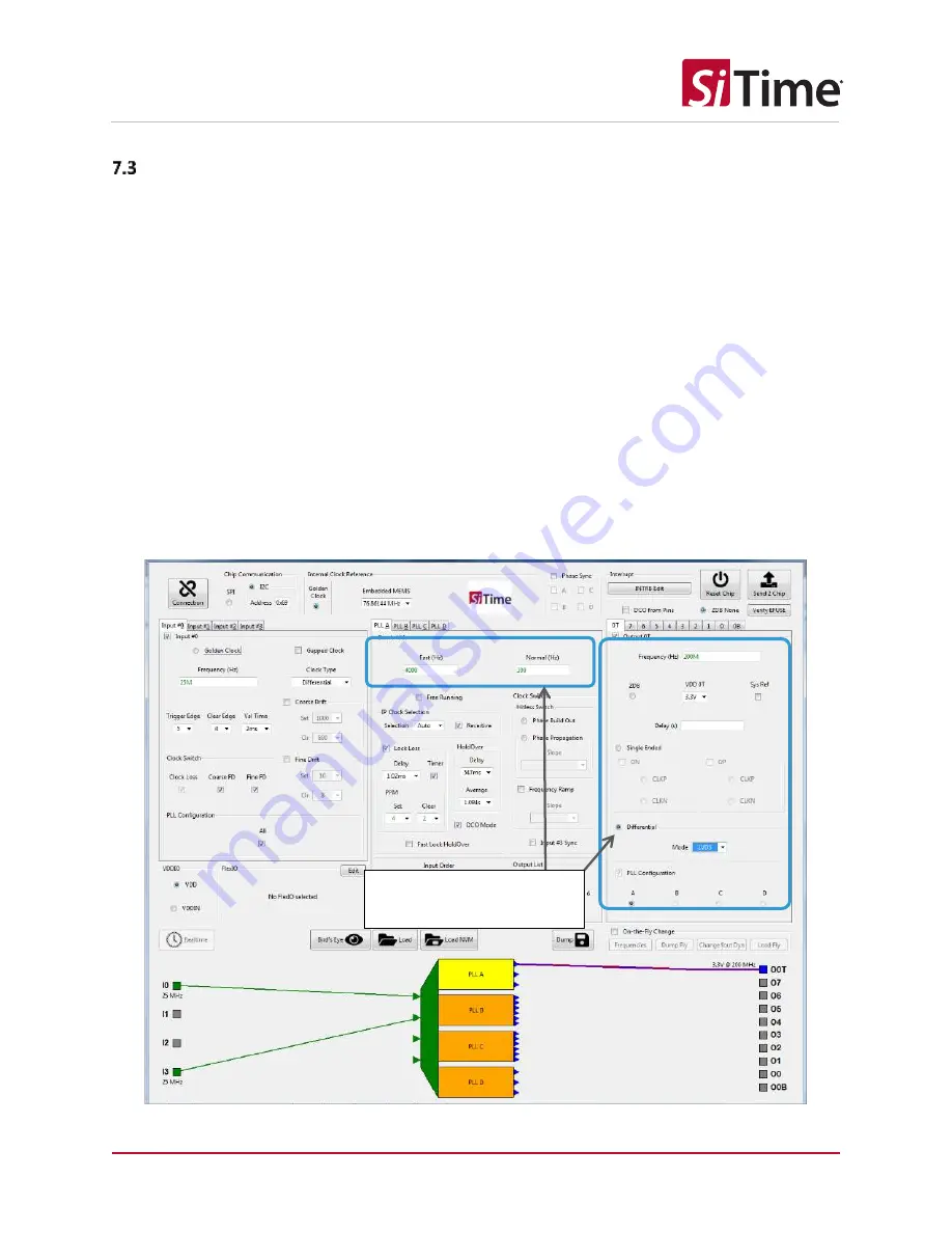
Click on a PLL and select its outputs. Then choose the PLL bandwidth, output frequency, output format
(differential, LVDS mode should be selected for the SiTime evaluation board used, see Table 1). Choose
the fast lock bandwidth and the regular bandwidth for the PLL. If you plan to use the DCO later, the DCO
should be enabled when configuring the PLL.
Once the list of input clocks to a PLL is finalized, the input clock priority for the PLL can be changed in
this section by dragging the clock selections up or down in the
Input Order
box (in the lower left area of
the PLL section). The priority of the input clocks is listed in order with the highest priority clock at the
top of the list and the lowest priority clock at the bottom.
For SiT95145
only
, the input clock switching can be set to either
Manual
or
Auto
in the
Selection
drop-
down menu in the
IP Clock Selection
area of the PLL section. For the
Auto
setting for the input clock
switching, the revertive switching can be enabled or disabled (non-revertive) by checking the
Revertive
checkbox.
Manual clock switching is supported by changing the respective
IN_SEL1/0
pins on the SiTime
SiT6503EB
Figure 31: Manual clock switching for SiT95145
Either of the sub-sections
can be selected for the PLL
system


