11
SimpliFire • SF-ALLP50-BK, SF-ALLP60-BK, SF-ALLP72-BK • 2044-980 Rev. C • 10/19
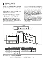
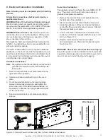
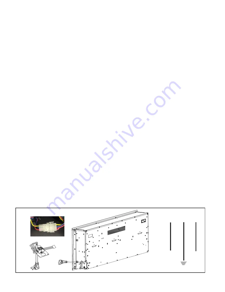
Figure 4.10 Optional Power Cord Assembly (Only for Direct Wall Mount Installation)
C. Electrical Connection / Installation
Note: All wiring must be completed prior to finishing
the unit.
All electrical connections shall be performed by a
qualified electrician.
WARNING! Risk of Fire, Electrical Shock and Injury!
Electrical wiring must comply with local building electri-
cal codes and the latest edition of the NFPA 70 National
Electric Code (NEC) other applicable regulations.
WARNING! Risk of Shock!
Label all wires prior to dis-
connection when servicing the appliance. Wiring errors
can cause improper and dangerous operation. Verify
proper operation after servicing.
This appliance has been designed to be hard-wired for
120VAC. A supplied plug-in kit is also available for use
with a grounded receptacle.
A 15 AMP, 120VAC/60Hz circuit is required. Additional
appliances on the same circuit as this appliance may ex-
ceed the current rating of that circuit. A dedicated circuit
is not required, but is strongly recommended to prevent
circuit breaker trips or fuse failure.
Hard-Wired Installation
:
Note
: The appliance must be electrically connected and
grounded in accordance with local building elec-
trical codes.
1. Remove terminal block cover plate located on the
right end of the appliance.
2. Install a wire strain relief bushing into the cover
plate.
3. Terminate type NM-B wire to the terminal block,
ensure connections are secure, and tighten the
strain relief. Use 3/32 slotted heat screwdriver, or
equivalent, to depress the spring loaded terminals
for the conductors.
4. Replace terminal block cover plate and retaining
screws.
WARNING!
Risk of Fire, Electrical Shock and Injury!
Ensure the power cord is not installed so that it is pinched
or against a sharp edge and ensure that the power cord is
stored or secure to avoid tripping and snagging.
Power Cord Installation
The appliance power cord has a three pin NEMA-5-15P
plug. The power cord should not be used unless a
grounded receptacle is available.
1. Remove the terminal block cover plate located on
the right end of the appliance.
2. Disconnect the terminal block from the three wires
inside the appliance. Wires are released by discon-
necting the three conductor wire connector. Discard
the terminal block cover plate.
3. Connect the three conductor wire connector to the
connector on the block supplied with the power cord
kit. See Figure 4.10.
4. Replace cord kit terminal block cover plate
and retaining screws. Plug cord into nearest outlet.
See Figure 3.3.
L
N
RED
YELLOW / GREEN
BLUE
Wire Diagram


