SimpliFire • SF-ALLP50-BK, SF-ALLP60-BK, SF-ALLP72-BK • 2044-980 Rev. C • 10/19
10
A. Appliance Preparation
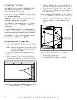
INTERIOR
SIDE PANEL
SCREWS (2)
Figure 4.2 Interior Side Panels Covering Attachment Points for
Recessed Mounting in 2 X 6 in. Framing
After determining the location and framing dimensions,
the appliance must be prepared for installation.
Remove appliance from packaging.
The appliance is shipped with the Trim Ring installed for
2 X 6 recessed installations.
NOTICE:
For optional wall mounting installations, ad-
ditional wall mount kit must be ordered.
If the appliance is to be recessed into 2 X 6 in. framed
wall construction, refer to Section 4.B for installation
instructions.
This appliance is not intended to be recessed into 2 X
4 in. framed wall construction. A minimum wall framing
and finishing material thickness of 5-3/4 in. is required.
If the appliance is to be installed directly to the face of
the wall, refer to Section 4.C for installation.
B. Recessed in 2 x 6 Framed Wall
1. Finish wall construction per requirements in Figure
4.1.
Note:
This appliance is inteded for use with no more
than 1 inch combined thickness of wallboard
and finishing materials.
2. Connect to electrical service. Reference Section
4.D.
3. Remove interior side panels on left and right of ap-
pliance by removing two (2) screws. See Figure 4.2.
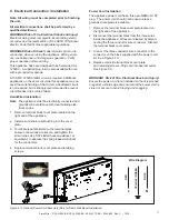
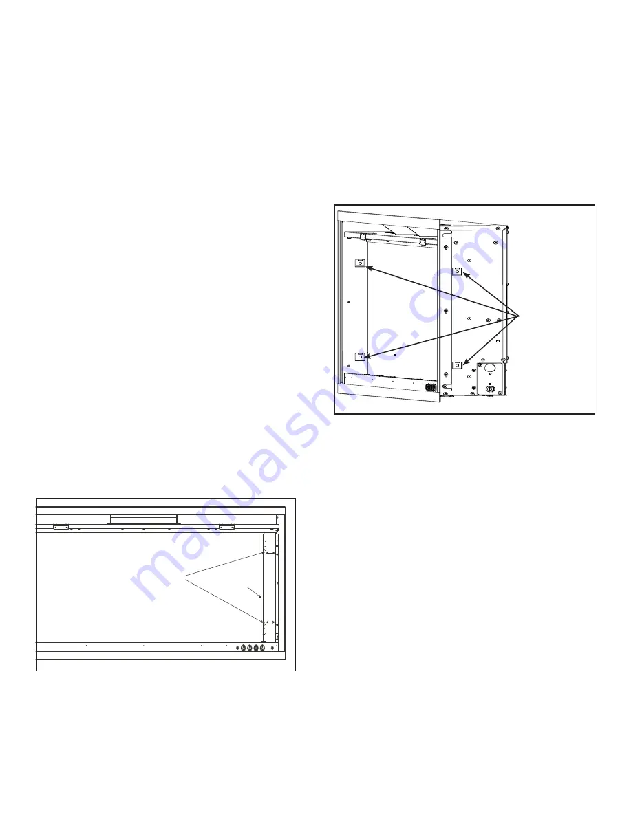
Figure 4.3 Securing the Appliance in 2 X 6 Framing
WOOD SCREW
TAB LOCATION
4. Install the appliance into the opening so the weight
of the appliance is supported by the bottom framing.
5. Level and plum the appliance using shims if neces-
sary. Ensure the Trim Ring is flush with wallboard or
wall finishing material.
Note:
The maximum distance from the back of the Trim
Ring to the face of the framing materials is 1 inch.
6. Once leveled, plum, and flush secure with four (4)
ST4X40 screws at the tabbed locations. See
Figure 4.3.
7. Reattach side panel covers.
8. See Section 4.E for Appliance Final Setup.


